Complete Installation Guide for Low-Temperature Valves
Low-temperature valves are critical components in liquefied natural gas (LNG), liquid oxygen, liquid nitrogen, and other cryogenic fluid transportation systems. Unlike conventional valves, low-temperature valves operate under unique conditions. They are installed at normal ambient temperature but must function in environments that may reach tens or even hundreds of degrees below zero. If the large temperature gradient is not properly managed, it may lead to valve seizure, seal failure, or even serious safety accidents. This article systematically introduces the key installation requirements of low-temperature valves to help engineering personnel avoid common problems and ensure safe and efficient system operation.
Special Structure and Principle of Low-Temperature Valves
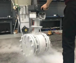
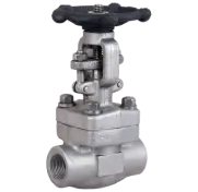
To understand the installation requirements of low-temperature valves, it is necessary to first examine their structural characteristics. The most distinctive feature of low-temperature valves is the extended bonnet design, also known as the long-neck bonnet.
Although it appears to be a simple structural extension, the long bonnet plays a critical role. It separates the operating components (handle or actuator) from the flow passage components (valve body and seat).
Why is this design necessary? Because cryogenic media have extremely low temperatures. If the bonnet is too short, cold energy will be directly conducted to the operating end, resulting in significant cold energy loss and posing a risk of frostbite to operators. By extending the bonnet, the packing chamber and the upper stem area can remain close to ambient temperature, protecting personnel safety while maintaining smooth operation.
However, this design also introduces new challenges. The ultra-long valve stem is more prone to deformation. When installed at room temperature, the stem may appear straight and smooth. But when the system enters cryogenic service, thermal contraction and stress changes may cause bending of the slender stem, which can lead to valve seizure. This is why low-temperature valve installation requires much stricter control compared to conventional valves.
Main Causes of Low-Temperature Valve Seizure
In practical engineering, valve seizure is one of the most common failures in cryogenic systems. To prevent this problem, its causes must be understood from design, installation, and operational perspectives.
1. Material Matching Issues in Design
The stem and stem sleeve of low-temperature valves are usually made of different materials. Valve stems are commonly made of stainless steel, with a linear expansion coefficient of approximately 1.73×10⁻⁶/℃, while stem sleeves are often made of brass, which has a coefficient as high as 19.9×10⁻⁶/℃.
This means that when the temperature drops from room temperature (20°C) to –162°C (the typical LNG temperature), the contraction differences are significant:
- Stainless steel stem contraction: approximately 0.3 mm per meter
- Brass sleeve contraction: approximately 3.6 mm per meter
The contraction of brass is more than ten times that of stainless steel. Under low-temperature conditions, the brass sleeve will shrink much more than the stainless steel stem. If the thread fit clearance is insufficient, the threads may become tightly seized.
This problem is especially common in concealed-stem structures and fine-pitch thread designs, where long thread engagement length, small clearance, and large temperature variation increase the risk of thread locking.
2. Mechanical Stress Caused by Improper Installation
Installation problems are often hidden but highly destructive.
- Pipeline alignment problems: If the valve is not properly aligned during installation, forced connection may introduce pre-stress. When the system cools down, pipeline contraction may superimpose additional stress onto the valve, causing body deformation.
- Lack of independent support: Cryogenic pipelines contract significantly during cooling. If the valve lacks independent support, it may move with pipeline displacement. The slender stem is unable to withstand lateral displacement and may bend.
- Incorrect rigid fixation: If the valve is rigidly connected to the insulation enclosure, deformation of the enclosure under low temperature may be transmitted directly to the valve body, damaging the concentricity between the stem and the body.
- Incorrect stem orientation: This is one of the most common installation errors. Cryogenic ball valves should never be installed horizontally (with the stem in horizontal position). Otherwise, cryogenic media may fill the extended bonnet cavity, leading to packing seal failure and direct conduction of cold energy to the handle, which may endanger operator safety.
3. Improper Operation During Service
Even if the design and installation are correct, improper operation may still cause failure.
- Incomplete warming treatment: Before system startup, valves must undergo thorough precooling and warming procedures. If moisture or temperature non-uniformity remains inside the valve, localized freezing may cause seizure.
- Excessive closing force: If the valve is closed too tightly at ambient temperature, the thread assembly may generate excessive clamping force after thermal contraction at low temperature, making reopening difficult.
- Packing chamber moisture ingress: If the valve packing gland is not properly sealed, moisture may penetrate and freeze under cryogenic conditions, directly locking the stem.
Key Requirements for Low-Temperature Valve Installation
Low-temperature valve installation must follow a series of specialized technical requirements covering selection, construction, and commissioning.
1. Optimization Suggestions for Design Selection
From an installation perspective, the following strategies can significantly reduce failure risk:
- Prefer rising-stem structures: External stem threads are less affected by media temperature and allow visual monitoring of valve position. Compared with concealed-stem designs, rising-stem valves are less prone to thread seizure.
- Use coarse trapezoidal threads: Coarse threads have larger pitch and higher strength, providing better tolerance to temperature variation. Although trapezoidal threads have slightly lower transmission efficiency than standard threads, they offer better self-locking performance and easier clearance adjustment after wear, making them more suitable for cryogenic service.
- Optimize material matching: In critical components, materials with closer thermal expansion coefficients should be considered, or sufficient thread clearance should be reserved during design to compensate for cryogenic contraction.
2. Key Considerations During Installation
- Stem orientation control: This is the primary installation principle for low-temperature valves. The stem must be installed within a vertical upward angle of 45 degrees, and installation on vertical pipelines should be avoided whenever possible. The optimal position is vertical upward or slightly inclined upward so that the extended bonnet cavity does not accumulate cryogenic liquid.
- Support structure requirements: Low-temperature valves must be equipped with independent and rigid supports fixed to building structures rather than pipelines. The support design must consider pipeline thermal contraction displacement, allowing relative movement between the pipeline and the valve while keeping the valve position stable.
- Flexible connection design: Connections between the valve and the insulation enclosure should adopt flexible methods such as metal hoses or sliding supports to prevent low-temperature deformation of the enclosure from being transmitted to the valve body, thus maintaining stem-body concentricity.
- Pipeline stress control: Ensure the valve is not subjected to external pipeline forces during installation. When flange connections are used, alignment must be accurate and bolts tightened uniformly. For large-diameter valves, temporary supports are recommended on both sides of the flange until the system stabilizes.
- Pressure relief direction verification: This is an extremely important but often overlooked step. Low-temperature valves are typically designed with pressure relief structures to release residual pressure inside the valve cavity. During installation, the relief direction must be carefully verified to ensure that:
The relief direction points to a safe zone and will not face operating passages or maintenance areas
The relief direction is consistent with process flow requirements to prevent leakage of flammable or toxic media
Relief openings are correctly installed; valves without relief ports may rupture when liquid vaporizes
Important reminder: The pressure relief direction must be clearly marked in process flow diagrams (P&ID) and piping isometric drawings, and verified before construction. This requirement is repeatedly emphasized because improper installation can lead to catastrophic consequences.
3. Commissioning and Operation Precautions
- Cold testing (cold adjustment): Before system commissioning, a no-load cooling test must be conducted. During low-temperature conditions, all valve operations should be checked. If sticking is observed, adjustments should be made promptly. Common methods include fine-tuning the flange fixing position on the valve enclosure and adjusting pipeline supports to ensure smooth operation.
- Drying treatment: Low-temperature valves must be completely dried before installation. If hydrostatic testing has been performed, strict drying procedures must be followed. First, purge with compressed air, then replace with dry nitrogen, and finally perform vacuum drying or fill with protective dry gas. If site conditions are limited, pneumatic testing is recommended to avoid residual moisture.
- Pre-cooling operation: Before system startup, valves must be cooled down slowly. The cooling rate should not be too rapid to avoid thermal stress caused by temperature gradients. During precooling, check for frost formation at packing glands and flange joints to detect leakage early.
- Operating force control: Follow the principle of "no leakage is acceptable" when closing valves. Do not apply excessive force. Materials become brittle under low temperature, and excessive torque may damage threads. If resistance is high during opening, stop operation immediately and investigate the cause rather than forcing the valve open.
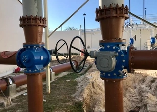
Special Installation Requirements for Cryogenic Ball Valves
Cryogenic ball valves are widely used in low-temperature systems due to their low flow resistance and excellent sealing performance, but they also have very strict installation requirements.
1. Horizontal Installation Is Strictly Prohibited
If the inner cavity of the extended bonnet is filled with cryogenic liquid, several hazards may occur:
- Vaporization of liquid increases internal pressure and damages packing seals
- Cold energy is directly conducted to the handle, creating frostbite risks
- Bonnet surface may frost or freeze, affecting operation
Therefore, cryogenic ball valves must be installed vertically with the stem facing upward. If site conditions are limited, the maximum inclination angle should not exceed 45 degrees, and the stem must remain higher than the valve body.
2. Upstream Pressure Relief Principle
Cryogenic ball valves usually adopt an upstream pressure relief design, meaning that when the valve is closed, the valve cavity communicates with the upstream pipeline to release pressure.
During installation, the following must be confirmed:
- Determine the upstream direction: The upstream side is not necessarily opposite to the flow direction but refers to the side bearing pressure when the valve is closed. For block valves installed on both sides of a control valve, the relief directions of the two valves should be opposite, each facing outward to its respective pipeline side.
- Maintain maintenance safety: This installation method ensures that during control valve maintenance, both block valves can be closed to release pressure into the pipelines on both sides, preventing process gas from being directly discharged into the atmosphere inside the valve chamber. Incorrect installation may lead to leakage of flammable or toxic media, causing environmental pollution or explosion hazards.
Summary and Recommendations
Low-temperature valve installation is a systematic engineering task that requires full lifecycle control from design, procurement, construction, to operation and maintenance. The core principles can be summarized as follows:
- Correct orientation: Stem must face vertically upward and pressure relief direction must be safe.
- Independent support: Use firm supports separated from pipeline displacement.
- Stress release: Employ flexible connections to avoid pre-stress.
- Thorough drying: Prevent freezing through strict drying procedures.
- Standardized operation: Ensure sufficient precooling and moderate closing force.
Engineering personnel are advised to carefully read the manufacturer's installation manuals before installation, verify special requirements in design drawings, and allocate sufficient time for adjustments during the cold trial stage. Owners should also strengthen construction quality supervision to ensure that key control points, such as pressure relief direction and support arrangement, comply with standards.
The safe operation of cryogenic systems largely depends on valve reliability. Through scientific installation and rigorous management, the seizure problems described above can be effectively avoided, ensuring long-term stable operation of low-temperature valves.
Send your message to this supplier
Related Articles from the Supplier
Complete Installation Guide for Y-Type Strainers
- Nov 06, 2025
Complete Guide to Safety Valve Selection
- Feb 12, 2026
Complete Guide to Three-Way Plug Valve
- May 29, 2026
Related Articles from China Manufacturers

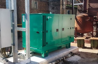
Complete Guide to Diesel Generator Set Installation
- Mar 25, 2026
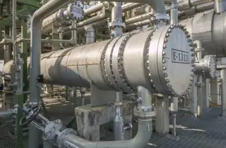
Complete Guide to Heat Exchanger Installation
- Oct 28, 2025

Complete Introduction of Pros of Forged Steel Valve
- Dec 23, 2016
Complete Guide to Forging Die Design
- Apr 03, 2026

Complete Guide to Infrared Sensors
- Aug 21, 2024
Related Products Mentioned in the Article
Zhejiang Kosen Valve Co., Ltd.
- https://www.kosenvalve.com/
- Business Type: Industry & Trading, Manufacturer,
Supplier Website
Source: https://www.kosenvalve.com/media-hub/complete-installation-guide-for-low-temperature-valves.html