Complete Guide to Check Valve Installation: Key Steps
In industrial production and daily life, pipeline systems are everywhere, and as an important component of the pipeline system, the check valve plays an indispensable role. It acts like a traffic police officer in the pipeline system, ensuring that the fluid can only flow in one direction, effectively preventing backflow, ensuring pipeline safety, and the normal operation of equipment. Today, let us take an in-depth look at the key points of check valve installation to help everyone better understand and apply this key equipment.
Basic Principle and Importance of Check Valves
The check valve, also known as a non-return valve or one-way valve, is an automatic valve. Its principle is very simple: it relies on the pressure of the flowing medium inside the pipeline to push the valve disc to achieve opening and closing. When the medium stops flowing, the valve disc automatically closes to prevent backflow of the medium inside the pipeline. This type of valve plays a vital role in ensuring pipeline safety, especially in water pump systems. It can ensure the correct flow direction of water inside the pump, thus ensuring the normal operation of the water pump.
Selection of Check Valve Installation Position
The installation position of the check valve is crucial, as different installation positions will lead to different effects. Generally speaking, the installation position of the check valve can be divided into two situations.
1. Installed Before the Pump
When the check valve is installed at the end of the vertical suction pipe before the pump, it is called a foot valve. The main purpose of this installation method is to prevent the water pump from needing to repeatedly draw water for priming during startup. Because when there is no water inside the pump and the suction pipe before the pump, the pump can only run idle and cannot draw water. By installing a foot valve, it can ensure that the pump is always filled with water, thereby enabling smooth pumping. This installation method is usually applicable to situations where the pump installation position is higher than the liquid level, also known as the negative pressure method.
2. Installed After the Pump
Another common installation method is to install the check valve behind the pump. This installation method is applicable to situations where the liquid level is higher than the pump. It can avoid the trouble of closing the pump outlet valve when starting and stopping the pump, especially suitable for main pipe water supply systems, effectively preventing backflow. In this case, the check valve must be installed at the pump outlet, before the outlet control valve, for easy maintenance. Generally, the first part of the pump outlet is a flexible connector (vibration damper), followed by the check valve, and then the isolation valve (such as butterfly valve, gate valve, globe valve, etc.).
Installation Sequence and Protection of Check Valves
The installation sequence of check valves is also very important. A correct installation sequence can not only protect the check valve itself but also protect other related equipment. Generally speaking, the check valve should be installed before the outlet gate valve or butterfly valve.
The advantage of this is that when one pump does not start and another pump starts, the impact force is borne by the gate valve or butterfly valve, thereby protecting the check valve. If the gate valve or butterfly valve is installed first, followed by the check valve, although the gate valve or butterfly valve can be protected, the check valve itself loses protection. The check valve operates by pressure difference. If the flow rate is unstable, the check valve will repeatedly open and close, which will affect the service life of the valve. Moreover, if the check valve fails, especially in a main pipeline system, it may be necessary to shut down the entire system for repair.
Installation of Different Types of Check Valves
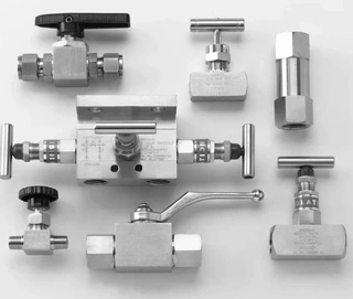
There are various types of check valves, and the installation points for each type are different. Understanding these points helps us better select and install suitable check valves.
1. Lift Check Valve Installation
The disc of the lift check valve slides along the vertical centerline of the valve body. This type of valve can only be installed on horizontal pipelines. The valve disc of a high-pressure small-diameter check valve can be spherical. The body shape of the lift check valve is the same as that of a globe valve, with a relatively large fluid resistance coefficient. Its structure is similar to that of a globe valve, and the valve body and valve disc are the same. The upper part of the disc and the lower part of the bonnet are provided with a guide sleeve, which can freely lift within the valve seat. When the medium flows forward, the valve disc is opened by the thrust of the medium; when the medium stops flowing, the valve disc automatically falls on the valve seat to prevent backflow. The inlet and outlet channel directions of the straight-through lift check valve are perpendicular to the valve seat channel direction; while the inlet and outlet channel directions of the vertical lift check valve are the same as the valve seat channel direction, with lower flow resistance than the straight-through type.
2. Swing Check Valve Installation
The disc of the swing check valve is disc-shaped and rotates around a pivot outside the valve seat passage. Since the internal passage of the valve is streamlined, the flow resistance is smaller than that of the lift check valve. This valve is suitable for low-velocity, large-diameter, irregular flow conditions but not suitable for pulsating flow, and its sealing performance is not as good as that of the lift type. Swing check valves are divided into single-disc, double-disc, and multi-disc types, mainly classified according to valve diameter, with the purpose of preventing hydraulic shock when the medium stops flowing or backflows. The installation position of the swing check valve is not restricted and can be installed on horizontal, vertical, or inclined pipelines. When installed on a vertical pipeline, the medium flow direction must be from bottom to top.
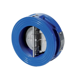
3. Wafer Check Valve Installation
The installation position of the wafer check valve is not restricted. It can be installed on horizontal pipelines, as well as vertical or inclined ones. This valve has a simple structure, small size, lightweight, easy operation, low fluid resistance, and good sealing performance. Wafer check valves are suitable for low-pressure, large-diameter applications, though installation conditions are limited.
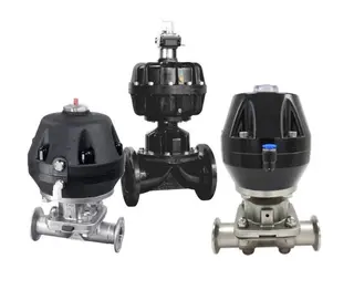
4. Diaphragm Check Valve Installation
The diaphragm check valve is suitable for pipelines prone to water hammer. The diaphragm can effectively buffer the water hammer caused by medium backflow, so it is generally used in low-pressure, normal-temperature pipelines, especially for water supply systems. The working medium temperature of diaphragm check valves is generally between -12℃ and 120℃, and the working pressure is less than 1.6MPa. However, diaphragm check valves can be made in large diameters, with DN sizes up to over 2000mm.
5. Ball Check Valve Installation
The ball check valve is suitable for medium- and low-pressure pipelines and can be made in large diameters. The valve body can be made of stainless steel, and the hollow ball sealing component can be wrapped with PTFE engineering plastic, so it can also be used in pipelines with mildly corrosive media. The working temperature range of the ball check valve is from -101℃ to 150℃, the nominal pressure does not exceed 4.0MPa, and the nominal diameter range is between 200mm and 1200mm.
Case Study
In one case, the valve plate of a butterfly valve in a factory's water pump system was broken. Investigation revealed that this was caused by improper installation of the check valve. The check valve had been installed after the butterfly valve, causing impact force to act directly on the butterfly valve when the pump started, leading to its damage. This case demonstrates that the installation position and sequence of the check valve are extremely important and must follow the correct procedures, otherwise serious consequences may occur.
Conclusion
Although the check valve is a small component, its role in the pipeline system cannot be underestimated. Correct installation position, sequence, suitable type selection, and regular maintenance are all key to ensuring the normal operation of the check valve. Through this article, it is hoped that readers can gain a deeper understanding of check valve installation, thereby better ensuring the safety of pipeline systems and the normal operation of equipment in practical applications.
When installing check valves, it is essential to select the appropriate valve type and installation position according to specific working conditions. At the same time, pay attention to the installation sequence to ensure the check valve receives proper protection. Only in this way can the check valve fully perform its function and ensure the safe and stable operation of the pipeline system.
Send your message to this supplier
Related Articles from the Supplier
Complete Guide to Safety Valve Selection
- Feb 12, 2026
Complete Guide to Three-Way Plug Valve
- May 29, 2026

A Complete Guide to Diaphragm Valve Maintenance
- Jan 06, 2026
Related Articles from China Manufacturers

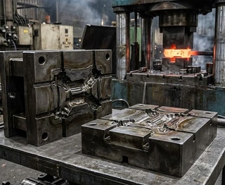
Complete Guide to Forging Die Design
- Apr 03, 2026
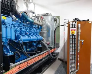
Complete Guide to Diesel Generator Wiring
- Sep 12, 2025
Complete Guide to Diesel Generator Testing
- Oct 15, 2025
Complete Guide to Diesel Generator Sets Voltage
- Oct 27, 2025
Related Products Mentioned in the Article
Zhejiang Kosen Valve Co., Ltd.
- https://www.kosenvalve.com/
- Business Type: Industry & Trading, Manufacturer,
Supplier Website
Source: https://www.kosenvalve.com/media-hub/complete-guide-to-check-valve-installation-key-steps.html