Steam Trap Back Pressure: Principles, Effects & Selection
A steam trap is a device designed to automatically discharge excess condensate from pipelines and is widely used in various industrial fields. Under normal operating conditions, when the amount of condensate inside the pipeline reaches a certain level, the steam trap opens to discharge the excess water outside the system. However, in practical applications, steam trap back pressure has a significant impact on trap operation, making it essential to understand its role.
Steam trap back pressure refers to the pressure acting on the downstream side of the steam trap during discharge. In simple terms, for a steam trap or valve, the downstream pressure is considered the back pressure,namely the outlet or secondary side pressure. The pressure difference between the steam trap inlet (primary side) and the back pressure is the working differential pressure. If the condensate at the steam trap outlet is discharged directly to the atmosphere, no back pressure will be generated.
Sources of Steam Trap Back Pressure
The back pressure of steam traps mainly originates from the following aspects:
1. System flow resistance
The system resistance within the condensate discharge pipeline is one of the primary causes of back pressure. When the resistance in the condensate pipeline is too large, condensate cannot be discharged in a timely manner, resulting in back pressure accumulation.
2. Localized resistance
Localized resistance in the condensate pipeline includes deposits on the pipe inner wall, rust particles, quartz crystallization, and other unavoidable factors. These resistances may cause the steam trap to remain in a partially open state or even prevent proper drainage.
In addition, even when condensate is discharged directly to the atmosphere, if the flow must pass through multiple elbows, flow resistance will still be encountered, which also contributes to back pressure formation. Reverse hydraulic head pressure can also generate back pressure. If the pressure inside a flash tank receiving condensate increases, the back pressure will also rise.
Specifically, back pressure may be generated by:
- Friction pressure produced by condensate and condensate transfer pipelines
- Flow resistance at pipeline elbows
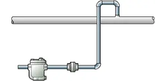
- Pressure generated by condensate climbing vertical pipelines
- Pressure inside pressurized equipment receiving condensate
The steam trap must transport condensate from equipment to a remote location, and therefore must overcome the head loss resistance during transportation. The combined resistance represents the back pressure value. Generally, a vertical lift of 10 meters corresponds to approximately 1 bar of head loss resistance. The back pressure generated during horizontal condensate transport is related to pipeline diameter, condensate pressure, and other parameters. Therefore, the total back pressure should be estimated based on actual operating conditions.
Influence of Back Pressure on Steam Trap Operation
- Effects on differential pressure and capacity: If the inlet (primary side) pressure remains stable, increasing back pressure will reduce the operating differential pressure of the steam trap. Since the discharge capacity of a steam trap increases with larger differential pressure, rising back pressure will directly reduce trap discharge capacity.
- Effects on valve operating condition: For most steam traps, back pressure generates a force acting in the valve opening direction. Compared with the force required to open the valve, if the inlet pressure remains unchanged while back pressure increases, the opening force will increase. This may cause certain types of steam traps to lose their ability to close properly, resulting in the valve remaining in an open state. The presence of back pressure reduces the actual working differential pressure of the steam trap, thereby affecting its fluid handling capacity. Under extreme conditions, when the inlet pressure is lower than the back pressure, flow stagnation may occur, preventing the trap from operating normally.
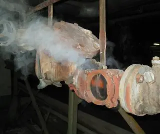
- Other adverse effects: When the steam trap stops functioning, back pressure downstream may cause condensate backflow, leading to corrosion and related problems. During system startup, back pressure downstream of the trap may sometimes be generated by water hammer oscillations on the condensate side, which can cause damage. Improper selection or inaccurate evaluation of steam trap back pressure may lead to slow heating rates, temperature fluctuations, heat exchanger vibration, corrosion, and noise.
Allowable Back Pressure of Steam Traps
Allowable back pressure refers to the maximum back pressure that still ensures normal operation of the steam trap, expressed as a percentage of the inlet (primary side) pressure. Generally, as back pressure increases, the steam trap gradually loses its normal operating capability.
1. Allowable Back Pressure for Different Steam Trap Types
Different types of steam traps have significantly different allowable back pressure ranges:
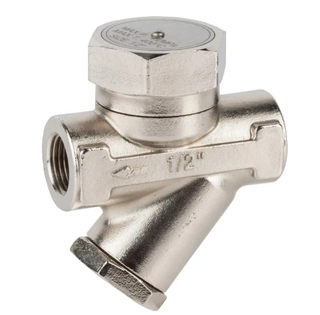
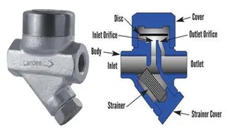
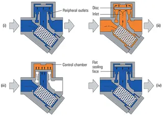
- Disc-type steam traps: The allowable back pressure typically ranges from 50% to 80% depending on product design. This means that if the inlet pressure is 1.0 MPaG, the back pressure must be less than approximately 0.5–0.8 MPaG.
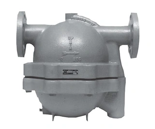
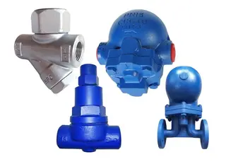
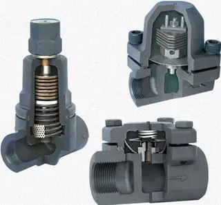
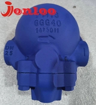
- Free float steam traps: These traps generally have much higher allowable back pressure, often exceeding 90%. If the inlet pressure is 1.0 MPaG, free float traps can still operate properly when the back pressure reaches up to 0.9 MPaG.
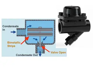
- Thermodynamic steam traps: The allowable back pressure is generally below 50% of the inlet pressure, and for impulse-type traps, it should not be less than 25%.
- Mechanical steam traps: These traps have strong back pressure resistance, allowing back pressure to exceed 95% of the inlet pressure, with an allowable back pressure ratio typically not less than 80%.
2. Back Pressure Ratio Calculation Formula
The back pressure ratio of a steam trap refers to the percentage ratio between the working back pressure (POB) and the working pressure (PO) during normal discharge operation:
Back pressure ratio = POB / PO × 100%
Back Pressure Considerations in Steam Trap Selection
After understanding the various effects of back pressure on steam trap operation, correctly considering back pressure factors during practical selection becomes a key step to ensure efficient system operation.
1. Basic Selection Principles
When selecting a steam trap, in addition to considering condensate discharge capacity, the back pressure at the planned installation location must also be evaluated. If system modification is required to recover condensate from an already installed steam trap, the trap will be subjected to higher back pressure, and discharge capacity and allowable back pressure must be fully considered.
2. Special Considerations for Condensate Recovery Systems
In closed condensate recovery systems, condensate is not directly discharged into an open condensate tank but is instead discharged into a sealed pressurized condensate tank, which increases back pressure.
For processes with large condensate flow, high heat exchange temperature, or applications where excessive subcooling is not allowed, free float or lever float steam traps are generally preferred.
Free float and lever float steam traps utilize the density difference between condensate and steam. The float moves up and down with condensate level changes, driving the valve disc to open or close, thereby achieving steam blocking and water discharge. Therefore, these types of traps can tolerate relatively higher back pressure.
3. Importance of Minimum Operating Differential Pressure
Proper selection of steam traps requires understanding the appropriate “minimum operating differential pressure” or “minimum usable pressure.” Sometimes, even if the steam trap is correctly selected, condensate stagnation may still occur periodically. This may be caused by control valve regulation or switching operations that interfere with trap performance.
Measures to Resolve Steam Trap Back Pressure Issues
To mitigate the impact of back pressure on steam trap systems, corresponding measures should be implemented as follows:
1. System Design Optimization
By modifying system design schemes and rationally planning pipeline layouts, system resistance can be reduced, thereby minimizing back pressure generation.
2. Regular Maintenance and Inspection
The condensate system should be inspected and maintained regularly to remove deposits inside the condensate pipeline and repair damaged components to prevent excessive back pressure.
3. Selection of High-Precision Steam Traps
Selecting steam traps with high-precision regulation capability can improve system control accuracy and reduce the likelihood of back pressure formation.
4. Special Case Handling
A typical application is reboiler condensate drainage. During reboiler heat exchanger design, a larger heat transfer area is often provided to compensate for fouling and thermal degradation during operation (usually enlarged by 30%–50%). Heat exchanger manufacturers may also provide more than 20% heat transfer area redundancy to ensure commissioning performance.
This leads to a situation where the heat exchanger may be oversized compared to actual demand. According to the heat transfer equation Q = KAΔT, when heat transfer rate Q remains constant and heat transfer area A is excessively large, the temperature difference ΔT must decrease. Consequently, the control valve reduces steam pressure demand. In extreme cases, steam pressure may become lower than the condensate back pressure downstream of the steam trap (even when the downstream pressure is atmospheric). Under such circumstances, a combination of a steam trap and mechanical pump is required to ensure proper condensate discharge.
Back Pressure Management in Practical Applications
Back pressure variation in parallel steam traps: When the discharge outlets of multiple steam traps are connected together, variations in condensate flow rate and condensate temperature will cause changes in steam trap back pressure.
Influence of flash steam: The most important factor is the generation of flash steam at the moment condensate is discharged. Flash steam is also one of the major contributors to back pressure formation.
Residual pressure recovery: In some cases, condensate is recovered using residual pressure downstream of the steam trap, or condensate is discharged into pressurized condensate pipelines or containers, which will also generate back pressure at the steam trap outlet.
Summary
Steam trap back pressure is a critical parameter in steam systems that cannot be ignored. It directly affects trap discharge capacity, operating performance, and service life. Understanding the sources, effects, and calculation methods of back pressure is essential for proper steam trap selection and operation.
In practical engineering, back pressure values should be calculated based on specific system conditions, appropriate steam trap types with suitable allowable back pressure should be selected, and effective measures should be taken to reduce the adverse effects of back pressure on the system. Only in this way can steam systems operate safely, efficiently, and stably while avoiding energy waste and equipment damage.
Particular attention should be paid to condensate recovery systems, where higher back pressure is usually present. Free float or lever float steam traps with higher allowable back pressure should be prioritized. Meanwhile, the minimum operating differential pressure must be fully considered to ensure that steam traps function properly under various operating conditions.
Send your message to this supplier
Related Articles from the Supplier
Maintenance Guide for Steam Trap Failures
- Oct 24, 2025
What is Bimetallic Steam Trap?
- Dec 26, 2025
What Is a Thermodynamic Steam Trap
- Jan 22, 2026

How to Prevent Leakage in Steam Trap?
- Sep 18, 2025
Related Articles from China Manufacturers
Essential Guide to Steam Trap Function and Selection
- Dec 10, 2024

Spirax Sarco Steam Trap FT14
- Nov 23, 2020
Check Valves in Steam Trap Systems
- May 07, 2024
What is a steam trap?
- Apr 25, 2019
Types of Steam Trap Valves
- May 11, 2023
How to Select and Install Steam Trap Valves
- Aug 16, 2023
Related Products Mentioned in the Article
Zhejiang Kosen Valve Co., Ltd.
- https://www.kosenvalve.com/
- Business Type: Industry & Trading, Manufacturer,
Supplier Website
Source: https://www.kosenvalve.com/media-hub/steam-trap-back-pressure-principles-effects-selection.html