Control Valve Leakage Classes Explained
In industrial piping systems, control valves play a central role in regulating fluid flow and pressure. Whether in petrochemical plants, power generation facilities, or water treatment systems, the performance of a control valve directly affects system safety, reliability, and operating economics. Among the many performance parameters used to evaluate control valves, seat leakage class is one of the most critical. It defines the valve's ability to restrict media leakage when in the fully closed position.
Selecting an appropriate leakage class influences not only procurement cost, but also operating efficiency, safety level, environmental compliance, and long-term maintenance expenses. A clear understanding of valve leakage classifications is therefore essential for proper valve selection, system commissioning, and ongoing operation and maintenance.
Differences Between Linear and Rotary Control Valves
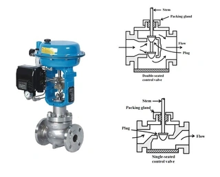
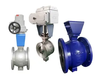
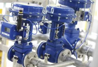
Control valves can be categorized into several structural types. Linear (sliding-stem) control valves, including single-seat, double-seat, and cage-guided valves, regulate flow by moving the plug vertically relative to the valve seat, changing the effective flow area. These valves are known for their simple structure and high control accuracy, but their flow capacity is comparatively limited.
Rotary (quarter-turn) control valves, such as automated ball valves and butterfly valves, are also widely used in control applications. In these designs, the closure element rotates rather than moves linearly. Rotary valves offer high flow capacity and low pressure loss, making them particularly suitable for large-diameter pipelines.
Due to these structural differences, the leakage characteristics of linear and rotary valves differ significantly, even when they are rated to the same leakage class.
Background of ANSI Leakage Class Standards
The original standard for control valve seat leakage classification was established by the American National Standards Institute (ANSI) and implemented by the Fluid Controls Institute (FCI) under the designation ANSI/FCI 70-2 (historically referenced as ANSI B16.104 FC170-2). This standard has since become an internationally recognized technical specification and is widely adopted by control valve manufacturers worldwide.
The primary purpose of establishing leakage class standards is to provide users and manufacturers with a uniform testing method to evaluate valve shutoff performance. Standardized test procedures allow meaningful comparison of sealing performance under identical conditions, offering an objective basis for valve selection.
It is important to note that leakage class test conditions differ from actual service conditions. Tests are typically conducted at ambient temperature (10–52 °C / 50–125 °F) and under specified pressure conditions. The results represent valve shutoff capability under standardized laboratory conditions, not absolute performance in real operating environments.
Technical Definitions of the Six Leakage Classes
ANSI/FCI 70-2 defines six leakage classes (Class I through Class VI), each with specific test methods and allowable leakage limits.
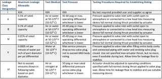
1. Class I Leakage
Class I represents the most basic leakage classification. When a valve is designed to meet its fundamental construction requirements, Class I allows certain deviations from Classes II, III, or IV. By agreement between purchaser and manufacturer, testing may even be omitted. This class is generally used in applications where leakage is not a critical concern.
2. Class II and Class III Leakage
Classes II and III are primarily intended for double-seat valves or pressure-balanced valve designs.
Class II allows leakage up to 0.1% of the rated valve capacity
Class III allows leakage up to 0.01% of the rated valve capacity
The test medium is air or water, with a test pressure of 45–60 psi (0.3–0.4 MPa) or the maximum operating pressure, whichever is lower. These classes are commonly specified for double-port, double-seat valves that do not use continuous pressure-balanced sealing elements such as O-rings.
3. Class IV Leakage
Class IV is the most commonly specified leakage class in industrial applications. It applies to both balanced metal-seated control valves with additional sealing features and unbalanced single-seat control valves.
Test conditions are the same as for Classes II and III, but allowable leakage is reduced to 0.01% of rated valve capacity. During testing, the valve outlet is vented directly to atmosphere or connected to a low-head-loss measuring device. The actuator must be adjusted to provide maximum rated closing force.
It is critical to understand that Class IV test results cannot be extrapolated to actual operating conditions. The test provides only a baseline measurement of shutoff capability at low differential pressure and ambient temperature. The “rated flow” refers to maximum flow at full rated stroke, not that the closed valve leaks 0.01% of its maximum capacity under service conditions.
4. Class V Leakage
Class V applies primarily to single-port, metal-seated control valves, both balanced and unbalanced, with special sealing designs. Unlike lower classes, allowable leakage in Class V depends on valve size and actual differential pressure across the closed valve.
Allowable leakage is calculated using the formula:
5 × 10⁻⁴ ml / (min·in·psi) or 5 × 10⁻⁴ m³ / (s·mm·MPa)
The test medium is water. Test pressure equals the maximum service differential pressure across the valve plug, limited by the ANSI pressure rating of the valve body, with a minimum of 100 psi (0.7 MPa). The valve must be completely filled with water, and pressure is applied only after the valve is fully closed. Actuator force is set to its maximum rated value but must not exceed it.
Because Class V testing is conducted at actual maximum shutoff differential pressure, it is particularly suitable for applications with high pressure drop across the seat. It also helps verify proper matching of valve and actuator, preventing erosion or stem pull-out caused by excessive closing forces.
5. Class VI Leakage
Class VI is the highest leakage class and is often mistakenly described as “bubble-tight” or zero leakage. In reality, Class VI still permits a defined amount of leakage, typically measured by counting air bubbles passing through a specified test tube per minute.
Class VI is most commonly applied to soft-seated (resilient-seated) valves, but it may also be specified for valves with other sealing arrangements.
The test medium is air or nitrogen at 50–125 °F (10–52 °C). Test pressure is the lower of the maximum rated plug pressure or 50 psi (0.35 MPa). In most power and process applications, 50 psi is used because actual seating forces in service are usually much higher. The actuator must be set to maximum closing force, and sufficient time must be allowed for leakage flow to stabilize.
Four Common Misconceptions About Leakage Classes
In engineering practice, there are several common misconceptions regarding control valve leakage classes that need to be clarified.
1. Class VI Is Always Tighter Than Class V
Although commonly believed, this is not always true. Depending on valve size and actual service differential pressure, Class V can be significantly more stringent than Class VI.
This is because Class V testing is conducted at actual maximum shutoff pressure, while Class VI testing is fixed at 50 psi. In high-pressure applications (e.g., 500 psi), Class V may impose far stricter leakage requirements.
2. Actuator Capability Is Always Sufficient
Some assume that control valve actuators can always generate enough force to fully seat the valve under varying pressure conditions. In reality, only Class V testing evaluates valve performance at actual maximum differential pressure, providing meaningful insight into valve–actuator matching after installation.
For other classes, users must rely on manufacturer sizing to ensure adequate actuator force under service conditions.
3. Leakage Classes Follow a Simple Decimal Relationship
While Class II allows ten times more leakage than Class III, and Class III ten times more than Class IV, this does not extend to Classes V and VI.
- Each class uses different definitions and units:
- Class IV: percentage of rated flow
- Class V: function of diameter and pressure
- Class VI: air bubbles per minute
- There is no direct decimal relationship among them.
4. Same Valve Size Means Same Leakage
Leakage allowance is often assumed to be the same for valves of equal size. In fact, different valve types have different Cv values and pressure recovery characteristics, resulting in different maximum flow capacities.
Since Classes I–IV specify leakage as a percentage of rated flow, allowable leakage varies by valve type. For Classes V and VI, leakage depends on minimum flow area. Typically, ball valves allow more leakage than butterfly valves, which allow more than globe control valves of the same nominal size.
Leakage Class Selection Under Different Operating Conditions
General Service Conditions: For non-hazardous media such as water or air, and systems that are not leakage-sensitive, Class III or Class IV usually provides an optimal balance between cost and performance.
High Differential Pressure and Severe Service: For applications involving high pressure drop, cavitation, or flashing risk, Class V is preferable because it reflects actual service pressure conditions more accurately.
Hazardous Media and Environmental Compliance: For toxic, valuable, or environmentally sensitive media, Class VI may be required. However, Class VI does not guarantee zero leakage. In extremely hazardous applications, additional measures such as double sealing, bellows seals, or series isolation and control valves may be necessary.
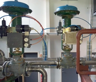
Relationship Between Actuator Selection and Leakage Class
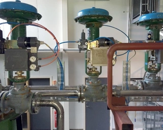
When selecting an actuator, it is essential to ensure that its output force or torque satisfies the sealing requirements of the chosen leakage class at maximum operating differential pressure.
For diaphragm actuators, special attention must be paid to spring settings and supply air pressure. A ball valve with a diaphragm actuator may fail to fully close if the air signal is insufficient. Unlike piston actuators, diaphragm actuators rely heavily on spring force to achieve tight shutoff.
Additionally, flow direction is critical. For globe control valves with diaphragm actuators, flow must enter under the plug. Otherwise, unbalanced forces may lift the plug off the seat, increasing leakage as pressure rises.
If a valve is tested to Class IV at 50 psi but operates at 500 psi in service, actual performance may differ greatly. The test only demonstrates acceptable shutoff at one-tenth of actual pressure, while available seating force under real conditions may be much lower.
Summary and Practical Recommendations
Control valve leakage class is a key indicator of shutoff performance. The ANSI/FCI 70-2 standard provides a unified framework for evaluating leakage from Class I to Class VI, each suited to specific valve designs and service conditions.
Rather than blindly pursuing the highest leakage class, engineers should select the most appropriate class based on actual operating conditions, media properties, safety requirements, and economic considerations. Key principles include:
- Consider actual differential pressure – prioritize Class V for high-pressure applications
- Match actuator capability – ensure sufficient closing force under service conditions
- Understand test limitations – standard tests do not equal real-world performance
- Differentiate valve types – same class does not mean same leakage across designs
Only through correct understanding and application of leakage class standards can control valves perform their intended function reliably, ensuring both safety and efficiency in industrial pipeline systems. For high-pressure or extreme-temperature services, close coordination with valve manufacturers is essential to avoid system failures or safety risks caused by improper leakage class selection.
Send your message to this supplier
Related Articles from the Supplier
Control Valve Leakage Classes Explained
- Jan 29, 2026
Common Problems in Pneumatic Control Valve Operation
- Feb 14, 2026
How to Choose the Right Control Valve
- Jan 12, 2026
What is Diaphragm Type Pneumatic Control Valve
- Jan 24, 2026
Industrial Safety Valve Blowdown Control Guide
- Apr 28, 2026
Related Articles from China Manufacturers

ANSI/FCI 70-2 Leakage Classes for Control Valves
- Jun 02, 2026
Control Valve Leakage: Testing and Standards
- Nov 18, 2025
Related Products Mentioned in the Article
Zhejiang Kosen Valve Co., Ltd.
- https://www.kosenvalve.com/
- Business Type: Industry & Trading, Manufacturer,
Supplier Website
Source: https://www.kosenvalve.com/media-hub/control-valve-leakage-classes-explained.html