Understanding Control Valve Fail-Safe Positions
In industrial production processes such as oil and gas, chemical engineering, and power generation, control valves are critical devices for regulating fluid flow and pressure. When a control system fails, control valves automatically move to a predefined fail-safe position. This design directly affects personnel safety, equipment integrity, and environmental protection. The main fail-safe positions include Fail Closed, Fail Open, and Fail in Place. Selecting the appropriate mode for control valves requires a comprehensive evaluation of process characteristics, media properties, risk consequences, and industry standards. In this article, we introduce the working principles, application scenarios, and selection methods of these three fail-safe modes, and also analyze real-world incidents such as signal loss failures to help engineers develop a correct fail-safe design philosophy.
Basic Concepts of Control Valve Fail-Safe Positions
The fail-safe position is a fundamental component of industrial safety systems. Its correct selection has a direct impact on personnel safety and equipment integrity. This section introduces the basic definition, the three modes, and their importance.
1. What Is a Fail-Safe Position?
A control valve fail-safe position refers to the predetermined position that a valve moves to when the control system fails. This design is a core part of industrial safety systems, intended to guide the process system toward a relatively safe state in abnormal situations such as power loss, signal failure, or instrument air failure.
A fail-safe position is not a simple mechanical setting; it is an engineering solution that must be verified throughout design, installation, commissioning, and maintenance. A correctly selected fail-safe position directly affects personnel safety, equipment protection, and environmental performance.
2. Three Main Fail-Safe Modes
Industrial standards define three basic fail-safe modes for control valves:
The first is Fail Closed (FC). When the control signal or power source is lost, the valve automatically closes, blocking fluid flow. This mode is used where leakage of hazardous media must be prevented.
The second is Fail Open (FO). When a failure occurs, the valve automatically opens, allowing continuous flow. This mode is used in critical systems where maintaining flow is essential.
The third is Fail in Place (FIP). When a failure occurs, the valve remains at its current position without movement. This mode is used in sensitive processes where system stability must be maintained.
3. Importance of Fail-Safe Design
Each fail-safe mode has a direct impact on personnel, equipment, and the environment. Improper selection can lead to serious consequences. For example, inappropriate Fail Open design may cause overflow or flooding of equipment. Incorrect Fail Closed design may result in abnormal pressure buildup. Fail in Place, while stable, may delay emergency response in some situations. Therefore, fail-safe selection must be based on comprehensive risk assessment and strict industry standards.

Detailed Explanation of the Three Fail-Safe Modes
Next, we explore the working principles, application scenarios, and potential risks of each mode. Fail Open, Fail Closed, and Fail in Place differ fundamentally in function and are suitable for different process requirements.
1. Fail Open Mode
Fail Open ensures that the valve opens when power or signal is lost, allowing fluid to continue flowing. Its primary purpose is to protect equipment or ensure safety.
In chemical plants, Fail Open is commonly used in cooling water systems. During a power outage, cooling water valves automatically open to maintain circulation, preventing overheating and damage to pumps due to no-flow operation. In emergency pressure relief systems, Fail Open design allows automatic discharge of media when pressure rises abnormally, preventing equipment rupture or explosion.
However, Fail Open also has limitations. In distillation columns and similar processes, a Fail Open valve may cause flooding during failure, reducing product quality and complicating downstream processing. Thus, while it provides protection, improper selection may introduce new process risks.
2. Fail Closed Mode
Fail Closed causes the valve to shut during system failure, blocking fluid flow. It is mainly used to prevent leakage, spillage, or hazardous media release.
Oil and gas systems widely adopt Fail Closed design to ensure that hazardous substances remain contained within pipelines during control failure. In hazardous chemical feed systems, Fail Closed can automatically cut off material supply in emergencies, preventing accident escalation.
However, Fail Closed also carries risks. Frequent closing may increase wear and reduce service life. Improper installation may cause water hammer effects, leading to pressure surges in piping systems. Operators require specialized training to understand system behavior after closure. Additionally, valve sticking or freezing can make maintenance difficult, while rapid pressure buildup can create safety hazards. Therefore, careful risk assessment is essential before selecting Fail Closed.
3. Fail in Place Mode
Fail in Place keeps the valve at its current position when a failure occurs. Its primary value is maintaining process stability and preventing disturbances caused by sudden valve movement.
This mode is suitable for systems requiring stable pressure or flow. In power plants, sudden valve position changes can cause severe steam flow fluctuations and potentially damage expensive equipment such as turbines. In chemical processes, feed valves to reactors often require stable positioning, as sudden changes can disrupt reaction equilibrium.
However, Fail in Place must be carefully evaluated. While it avoids sudden disturbances, it may delay critical shutdown or emergency relief actions when immediate intervention is required.
Methods for Selecting Fail-Safe Positions
Selection requires a comprehensive evaluation of safety factors, process conditions, industry standards, and application experience.
1. Safety and Process Considerations
The first step is failure consequence analysis. Engineers must determine whether leakage, blockage, or overpressure could occur under failure conditions and evaluate the associated risks.
Second, fluid properties must be analyzed. High-temperature, toxic, or corrosive media generally require Fail Closed to prevent exposure and environmental damage. For non-hazardous media such as cooling water or inert gases, Fail Open may be more appropriate.
Third, redundancy requirements must be considered. Critical safety loops often require multiple layers of redundancy, where the fail-safe position of a single valve is only part of the overall safety system.
Fourth, maintenance accessibility is important. Valves must be easily inspectable; otherwise, fail-safe functionality may degrade due to poor maintenance.
2. Industry Standards and Regulations
Fail-safe selection must comply with relevant standards. Organizations such as API (American Petroleum Institute), ASME (American Society of Mechanical Engineers), and ISO (International Organization for Standardization) provide clear guidance on control valve design.
In safety instrumented systems, IEC 61508 and IEC 61511 define functional safety lifecycle management frameworks. These standards require systematic evaluation of fail-safe functions, including Hazard and Operability Studies (HAZOP) and Safety Integrity Level (SIL) assessments.
Documentation is also required, including risk assessments, design basis reports, and validation test results.
3. Industry Application Examples
In refineries, cooling water systems typically use Fail Open design. During a plant-wide power failure, valves open automatically to maintain circulation and prevent heat buildup in reactors and heat exchangers.
Fuel gas systems commonly use Fail Closed design. In case of failure, valves immediately shut off fuel supply to prevent fire or explosion hazards.
In power plants, certain steam control valves adopt Fail in Place design. Sudden flow changes may damage turbine blades, so maintaining position avoids mechanical stress.
In food processing plants, a balance must be achieved between safety and production loss. Protecting personnel may require shutdown and product loss, and such priorities must be defined during design.
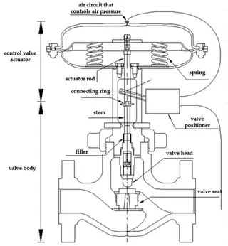
Role of Actuators and Springs
Fail-safe operation depends heavily on actuator design and spring mechanisms. Pneumatic, hydraulic, and electric actuators achieve fail-safe behavior differently, while springs play a central role.
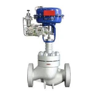
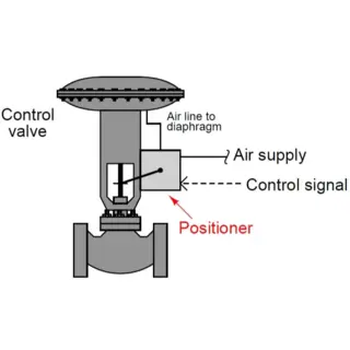
1. Pneumatic Actuators
Pneumatic actuators are the most common control valve drivers, using compressed air as the energy source. They can be configured for Fail Open or Fail Closed depending on spring arrangement and air action direction.
Under normal operation, air pressure overcomes spring force to position the valve. When air is lost, the spring releases stored energy and drives the valve to its safe position.
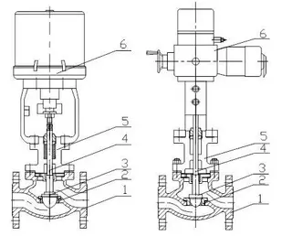
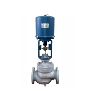
2. Hydraulic and Electric Actuators
Hydraulic actuators use liquid as the transmission medium and provide high output force and fast response. Fail-safe positioning is achieved using accumulators or spring systems.
Electric actuators are driven by motors. Some include batteries or spring energy storage to move the valve to a safe position during power loss. However, not all electric actuators are fail-safe, so confirmation is essential during selection.
3. Critical Role of Springs
Springs are the core element of fail-safe systems. During normal operation, they are compressed or extended, storing mechanical energy. When failure occurs, they release energy to drive the valve.
Spring-return actuators are the most common fail-safe design. Spring condition directly affects reliability. Fatigue, corrosion, or damage may prevent proper fail-safe action. Therefore, regular inspection and preventive maintenance are essential.
Signal Loss Incident Analysis and Prevention
In engineering practice, signal loss is one of the most common causes of fail-safe malfunction. These issues often arise from discrepancies between design assumptions and field conditions.
1. Typical Case Study
In a chemical plant, a control valve was designed to Fail Closed upon signal loss. However, when the DCS analog output dropped below the minimum operating range of the smart positioner, the positioner lost power. Instead of closing, the valve remained fully open, causing an immediate plant shutdown.
Investigation revealed that only loop checks and stroke tests had been performed during commissioning. Signal loss behavior was never physically tested. Additionally, actuator action settings had been modified during calibration without revalidating fail-safe behavior.
This demonstrates that proper control performance does not guarantee correct fail-safe operation.
2. Limitations of Conventional Testing
Standard commissioning tests focus on signal tracking, linear response, and automatic control stability. These tests evaluate control accuracy, not failure behavior.
True signal loss scenarios require simulation of complete signal interruption, power loss, and instrument air failure. Without these tests, fail-safe behavior remains theoretical.
3. Hidden Risks of Smart Positioners
Smart positioners improve control performance but introduce configuration risks. Parameters such as action direction and signal range are often adjusted during commissioning.
These changes may unintentionally alter fail-safe behavior. Many failures occur months after commissioning when original configuration changes were never validated under failure conditions.
4. Troubleshooting and Verification Methods
A step-by-step validation approach should be used.
First, simulate real signal loss by forcing analog output below operating range and observe actual valve response.
Second, test different failure modes separately, including signal loss, power loss, and air supply loss.
Third, review the full control chain, including DCS output logic, positioner settings, actuator action, and pneumatic connections.
5. Engineering Corrective Actions
Corrective measures should focus on predictability rather than simple restoration of function.
Fail-safe positions must be physically verified under real failure conditions. Each valve must be tested for signal, power, and air loss scenarios.
Control logic should be simplified. Excessive inversion logic increases risk. DCS should define actuator action clearly, while positioners should remain in standard configuration where possible.
Any configuration change must trigger revalidation of fail-safe behavior.
DCS output range must be engineered properly to avoid unintended signal drops.
Finally, fail-safe validation should be part of acceptance criteria, not just commissioning procedures.
Conclusion
Selection of control valve fail-safe positions is a fundamental yet often overlooked aspect of industrial safety design. Fail Closed, Fail Open, and Fail in Place each serve specific purposes, and no single mode is universally optimal. Selection must be based on failure consequence analysis, fluid characteristics, industry standards, and full lifecycle verification.
Special attention must be given to smart positioner configuration changes and DCS signal range settings, as both can alter fail-safe behavior. Any modification requires revalidation.
Ultimately, fail-safe design cannot remain theoretical. Only through physical testing under real failure conditions can engineers ensure that control valves reliably protect personnel, equipment, and the environment when failures occur.
Send your message to this supplier
Related Articles from the Supplier

Understanding Control Valve Fail-Safe Positions
- Jun 04, 2026

Understanding Pneumatic Control Valve Principles
- May 13, 2024
A Quick Understanding of Control Valves
- Apr 26, 2024
Related Articles from China Manufacturers

Related Products Mentioned in the Article
Supplier Website
Source: https://www.valvecontrol.cn/news/understanding-control-valve-fail-safe-positions.html