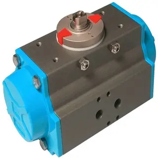
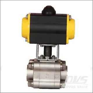
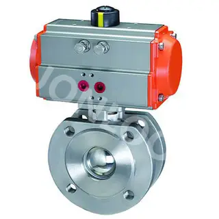
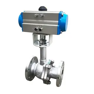
Pneumatic Valve Actuator

Key Specifications / Features
China Pneumatic Valve Actuator Manufacturer offers 14 types Pneumatic Valve Actuators, spring actuator, double acting torque, 2.5-8 Bar, ISO 5211 Dimesions.
Request a quote
Detail Information

Pneumatic Valve Actuator Analysis diagram
Pneumatic Valve Actuator Description:
14 Types ( DA 32- DA 270 ).
Offering a broad range of pneumatic rack & pinion actuators.
The ports are NAMUR standard for easy solenoid valve connection.
ISO 5211 dimensions on all sizes.
All internal and external surfaces are anodized for corrosion resistance.
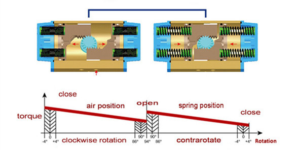
Actuator have a regulation range from-4° to +4°.
Shaft bearings isolate the pinion gear from the housing and support the shaft for high cycle.
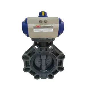
Actuator can be lifted on many styles of quarter-turn valve, including ball, butterfly and plug and dampers.
Pneumatic Valve Actuator Operation:
Working pressure: 2.5 Bar – 8 Bar.
Working Temputure:
Standard range: -20℃ - +80℃.
Low temperature range: -40℃ - +80℃(HNBR).
High temperature range: -20℃ - +150℃(vition).
Factory lubricated for life under normal vorking.
Operating media – Dry or lubricated air, non-corrosive and inert gas or light hydraulic oil.
Angle of rotation: 0° to -90°± 4°.
| MOD. | ISO5211 | A | B | C | D | E | F | G | H | I | J | K | L | M | N | O ISO7/1 |
P | Q | R | S |
| 50 | FO3-FO5 | 138 | 30 | 41 | 69.5 | 20 | 30 | 80 | 26.5 | 36 | 50 | 11 | M6*9 | M5*7.5 | 12 | 1/8’’ | 12 | 16 | M5*7 | 11 |
| 63 | FO5-FO7 | 162 | 35.5 | 45 | 80.5 | 20 | 30 | 80 | 27.5 | 50 | 70 | 14 | M8*12 | M6*8 | 16 | 1/8’’ | 12 | 16 | M5*7 | 11 |
| 75 | FO5-FO7 | 208 | 42 | 52.5 | 97 | 20 | 30 | 80 | 35 | 50 | 70 | 17 | M8*12 | M6*8 | 19 | 1/8’’ | 12 | 16 | M5*7 | 17 |
| 88 | FO5-FO7 | 245 | 49 | 60 | 115.5 | 20 | 30 | 80 | 46 | 50 | 70 | 17 | M8*12 | M6*8 | 19 | 1/8’’ | 12 | 16 | M5*7 | 17 |
| 100 | FO7-FO10 | 266 | 55 | 68 | 121.5 | 20 | 30 | 80 | 50 | 70 | 102 | 17 | M10*14 | M8*12 | 20.5 | 1/4’’ | 12 | 16 | M5*7 | 17 |
| 115 | FO7-FO10 | 310 | 64 | 73 | 141.5 | 30 | 30 | 130 | 50 | 70 | 102 | 22 | M10*14 | M8*12 | 24 | 1/4’’ | 12 | 16 | M5*7 | 17 |
| 125 | FO7-FO10 | 340 | 68 | 80 | 153.5 | 30 | 30 | 130 | 61 | 70 | 102 | 22 | M10*14 | M10*15 | 24 | 1/4’’ | 12 | 16 | M5*7 | 22 |
| 145 | FO10-FO12 | 401 | 78.5 | 90 | 179 | 30 | 30 | 130 | 73 | 102 | 125 | 27 | M12*18 | M10*15 | 29 | 1/4’’ | 12 | 16 | M5*7 | 22 |
| 160 | FO10-FO12 | 430 | 86.5 | 100 | 192 | 30 | 30 | 130 | 83.5 | 102 | 125 | 27 | M12*18 | M16*25 | 29 | 1/4’’ | 12 | 16 | M5*7 | 27 |
| 180 | F14 | 482 | 102 | 102 | 222 | 30 | 30 | 130 | 60 | 140 | --- | 36 | --- | M16*25 | 39 | 1/4’’ | 12 | 16 | M5*7 | 27 |
| 200 | F14 | 532 | 112 | 112 | 244 | 30 | 30 | 130 | 63 | 140 | --- | 36 | --- | M20*30 | 39 | 1/4’’ | 12 | 16 | M5*7 | 30 |
| 240 | F16 | 662 | 133 | 133 | 288 | 30 | 30 | 130 | 85 | 165 | --- | 46 | --- | M20*30 | 49 | 3/8’’ | 20 | 22.5 | M6*8 | 30 |
| 270 | F16 | 730 | 153 | 153 | 323 | 30 | 30 | 130 | 106 | 165 | --- | 46 | --- | --- | 49 | 1/2’’ | 20 | 22.5 | M6*8 | 30 |
Pneumatic Valve Actuator Parts List
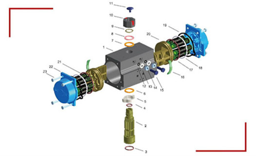
| Item | description | material | coating | quantity(DR) | quantity(SR) |
| 1 | body | extruded aluminium | anodic oxidation | 1 | 1 |
| 2 | pinion | WCB | nickel pLated | 1 | 1 |
| 3 | o-ring | NBR70 | ----- | 1 | 1 |
| 6 | pinion bearing | POM | ----- | 1 | 1 |
| 5 | position cam | SS304 | ----- | 1 | 1 |
| 4 | upper o ring | NBR70 | ----- | 1 | 1 |
| 7 | pinion bearing | POM | ----- | 1 | 1 |
| 8 | pinion ring | SS304 | ----- | 1 | 1 |
| 9 | jump ring | SS304 | ----- | 1 | 1 |
| 10 | indicator | Nylon | ----- | 1 | 1 |
| 11 | indicator screw | Nylon+SS STEEL | ----- | 1 | 1 |
| 18 | guide ring | POM | ----- | 1 | 1 |
| 17 | piston 0-ring | NBR70 | ----- | 1 | 1 |
| 16 | piston thrust block | POM | ----- | 2 | 2 |
| 20 | piston | forget aluminium | ----- | 2 | 2 |
| 19 | end cap o-ring | NBR70 | ----- | 2 | 2 |
| 22 | end cap | forget aluminum | power painting | 2 | 2 |
| 23 | end cap screw | SS304 | ----- | 2 | 2 |
| 15 | regulation screw | SS304 | ---- | 2 | 2 |
| 14 | nut | SS304 | ----- | 2 | 2 |
| 813 | washer | SS304 | ----- | 8 | 8 |
| 12 | o ring | NBR70 | ----- | 2 | 2 |
| 21 | spring | spring steel | phosphating | N/A | Max.12 |
Spring Actuator
Spring actuator Table Summary
| Model | Group | Spring Torque (Nm) |
Air Pressure(bar) | ||||||||||||||||||||||||||
| 3 | 4 | 5 | 5.5 | 6 | 7 | 8 | |||||||||||||||||||||||
| Pneumatic Torque(Nm) | |||||||||||||||||||||||||||||
| 0° | 90° | 0° | 90° | 0° | 90° | 0° | 90° | 0° | 90° | 0° | 90° | 0° | 90° | 0° | 90° | ||||||||||||||
| SR50 | 3/3 | 4 | 5.8 | 5.9 | 4.1 | 9.3 | 7.4 |
12.6 | 10.8 | 14.2 | 12.4 | ||||||||||||||||||
| 4/4 | 5.4 | 7.8 | 7.9 | 5.5 | 11.2 | 8.8 | 12.9 | 10.5 | 14.6 | 12.1 | 17.9 | 15.5 | |||||||||||||||||
| 5/5 | 6.7 | 9.7 | 9.9 | 6.9 | 11.5 | 8.5 | 13.2 | 10.2 | 16.5 | 13.5 | 19.8 | 16.8 | |||||||||||||||||
| 6/6 | 8.1 | 11.7 | 10.2 | 6.6 | 11.9 | 8.2 | 15.2 | 11.6 | 18.5 | 14.9 | |||||||||||||||||||
| SR63 | 3/3 | 7 | 10.1 | 10.9 | 7.5 | 16.8 | 13.3 | 22.7 | 19.2 | 25.6 | 22.1 | ||||||||||||||||||
| 4/4 | 9 | 13.5 | 14.6 | 10 | 20.4 | 15.8 | 23.4 | 18.7 | 26.3 | 21.7 | 32.2 | 27.5 | |||||||||||||||||
| 5/5 | 11.1 | 16.9 | 18.2 | 12.4 | 21.1 | 15.4 | 24.1 | 18.3 | 29.9 | 24.2 | 35.8 | 30 | |||||||||||||||||
| 6/6 | 13.3 | 20.2 | 18.9 | 12 | 21.9 | 14.9 | 27.7 | 20.8 | 33.6 | 26.7 | |||||||||||||||||||
| SR75 | 3/3 | 13.2 | 20.8 | 21.6 | 14.1 | 33.3 | 25.8 | 44.9 | 37.4 | 50.7 | 43.2 | ||||||||||||||||||
| 4/4 | 17.7 | 27.7 | 28.8 | 18.8 | 40.5 | 30.5 | 46.3 | 36.3 | 52.1 | 42.1 | 63.7 | 53.7 | |||||||||||||||||
| 5/5 | 22.1 | 34.6 | 36.1 | 23.6 | 41.9 | 29.4 | 47.7 | 35.2 | 59.3 | 46.8 | 71 | 58.5 | |||||||||||||||||
| 6/6 | 26.5 | 41.5 | 37.5 | 22.4 | 43.3 | 28.3 | 54.9 | 39.9 | 66.5 | 51.5 | |||||||||||||||||||
| SR88 | 3/3 | 22 | 34.7 | 32.9 | 20.3 | 51.2 | 38.6 | 69.5 | 56.9 | 78.7 | 66 | ||||||||||||||||||
| 4/4 | 29.3 | 46.2 | 43.9 | 27 | 62.2 | 45.3 | 71.3 | 54.5 | 80.5 | 63.6 | 98.8 | 81.9 | |||||||||||||||||
| 5/5 | 36.7 | 57.8 | 54.8 | 33.8 | 63 | 42.9 | 73.1 | 52.1 | 91.5 | 70.4 | 109.8 | 88.7 | |||||||||||||||||
| 6/6 | 44 | 69.3 | 56.7 | 31.4 | 65.8 | 40.5 | 84.1 | 58.8 | 102.4 | 77.1 | |||||||||||||||||||
Double Acting Torque Table Summary
_%E5%89%AF%E6%9C%AC.jpg)
Double Acting Torque Table Summary
| Double Acting Torque | ||||||||
| 型号 | Air Pressure(Bar) | |||||||
| 2.5 | 3 | 4 | 5 | 5.5 | 6 | 7 | 8 | |
| Torque Values(N.M) | ||||||||
| DA32 | 3.5 | 4.2 | 6 | 7.5 | 8 | 9 | 10 | 11.5 |
| DA50 | 8.3 | 10 | 13.3 | 16.6 | 18.3 | 19.9 | 23.3 | 26.6 |
| DA63 | 14.7 | 17.6 | 23.5 | 29.3 | 32 | 35.2 | 41 | 46.9 |
| DA75 | 29 | 35 | 46.5 | 58.2 | 64 | 70 | 82 | 93 |
| DA88 | 45.8 | 54.9 | 73.2 | 91.5 | 101 | 110 | 128 | 146 |
| DA100 | 66 | 79.8 | 106 | 133 | 146 | 160 | 186 | 213 |
| DA115 | 107 | 129 | 172 | 215 | 236 | 258 | 301 | 344 |
| DA125 | 138 | 166 | 222 | 277 | 305 | 332 | 388 | 443 |
| DA145 | 217 | 261 | 348 | 435 | 478 | 522 | 609 | 696 |
| DA160 | 284 | 340 | 454 | 567 | 324 | 681 | 794 | 908 |
| DA180 | 383 | 459 | 613 | 766 | 842 | 919 | 1072 | 1225 |
| DA200 | 532 | 638 | 851 | 1064 | 1170 | 1276 | 1489 | 1702 |
| DA240 | 1160 | 1392.5 | 1857 | 2321 | 2553 | 2785 | 3249 | 3713 |
| DA270 | 1132 | 1958 | 2611 | 3264 | 3590 | 3916 | 4569 | 5222 |
Send your message to this supplier
FAQs
Similar Products
Related Searches
Products you might also like

-320x320.webp)
Supplier Website
Source: https://www.valves-uk.com/pneumatic-valve-actuator.html