
Understanding Pneumatic Control Valves: Key Components and Operation Guide
Introduction
Modern industrial operations depend on precise and stable flow control to maintain safety, efficiency, and consistent product quality. Industries such as oil and gas, petrochemical processing, chemical manufacturing, power generation, water treatment, food processing, pharmaceuticals, and mining all require reliable regulation of pressure, temperature, flow rate, and liquid level under complex and often harsh conditions. Among various automation components, pneumatic control valves have become one of the most widely used solutions due to their performance and versatility.
Pneumatic control valves operate using compressed air to drive an actuator that accurately positions the valve for flow regulation. Compared with electric actuators, they offer faster response, simpler structure, and greater suitability for demanding industrial environments. Since compressed air is widely available in plants, these valves provide a cost-effective and dependable control method.
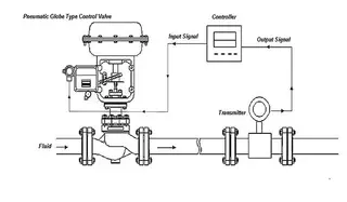
As final control elements in process loops, they receive signals from controllers or DCS systems and adjust flow accordingly, ensuring stable and efficient operation across diverse industries and applications.
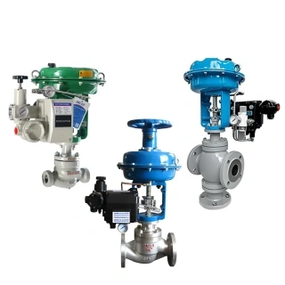
What Is a Pneumatic Control Valve?
A pneumatic control valve is a type of automated valve that uses compressed air to actuate and regulate the flow of gases, liquids, steam, or slurry within a piping system. The valve changes the size of the flow passage by moving internal components such as plugs, discs, or balls, thereby controlling process variables including pressure, temperature, flow rate, and fluid level.
The actuator converts pneumatic energy into mechanical motion. This motion drives the valve stem and valve closure member to open, close, or partially position the valve according to process requirements. The valve typically receives a control signal from an instrument controller, which determines the desired valve position based on real-time process conditions.
Pneumatic control valves are especially popular in hazardous environments because compressed air does not create sparks or electrical ignition sources. This makes them highly suitable for explosive or flammable applications commonly found in oil refineries, chemical plants, offshore platforms, and gas processing facilities.
The primary function of a pneumatic control valve is to control airflow or fluid movement within a pneumatic or process control system. Depending on system requirements, the valve may regulate:
- Flow rate
- Pressure
- Temperature
- Fluid direction
- Liquid level
- Process stability
Pneumatic valves can also operate as directional control valves that route compressed air to different components in automated systems. In industrial automation, they help coordinate machine operations, cylinder movements, and production processes.
Main Components of Pneumatic Control Valves
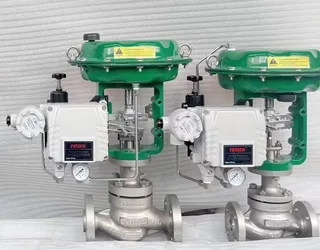
A pneumatic control valve consists of several essential components that work together to provide accurate flow control and reliable operation.
Valve Body
The valve body forms the pressure-containing shell of the valve and houses the internal trim components. It directs the process fluid through the valve and withstands pressure, temperature, and corrosion conditions. Valve body materials vary depending on the application and may include carbon steel, stainless steel, duplex stainless steel, alloy steel, bronze, or special corrosion-resistant alloys.
Valve Trim
The trim refers to the internal flow-controlling parts, including:
- Valve plug
- Seat
- Cage
- Stem
- Disc
The trim design determines the valve’s flow characteristics, pressure drop capability, sealing performance, and resistance to wear or cavitation.
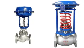
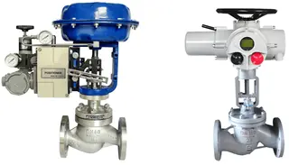
Pneumatic Actuator
The actuator converts compressed air pressure into mechanical movement. Common actuator types include:
- Diaphragm actuators
- Piston actuators
- Rotary actuators
The actuator determines the valve’s response speed, force output, and fail-safe action.
Positioner
A valve positioner improves control accuracy by ensuring that the valve stem position matches the controller signal. It compensates for friction, pressure fluctuations, and actuator nonlinearities.
Air Supply System
The compressed air system supplies clean, dry air to the actuator. Filters, regulators, and lubricators are commonly used to maintain air quality and stable operating pressure.
Accessories
Additional accessories may include:
- Solenoid valves
- Limit switches
- Air boosters
- Volume tanks
- Smart controllers
- Pressure transmitters
These devices enhance automation capabilities and improve overall control performance.
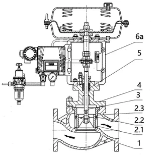
Working Principle of Pneumatic Control Valves
The operation of a pneumatic control valve is based on the interaction between compressed air pressure and the actuator mechanism. When the controller sends a signal, the positioner converts it into pneumatic pressure that acts on the actuator diaphragm or piston.
The actuator movement then drives the valve stem, changing the valve opening and regulating fluid flow through the valve.
The valve continuously adjusts its position to maintain the desired process condition. For example:
- If temperature rises above the setpoint, the valve may reduce steam flow.
- If pressure drops, the valve may open further to increase flow.
- If liquid level becomes too high, the valve may partially close.
- This constant adjustment enables stable and precise process control.
Air-to-Open and Air-to-Close Valve Actions
Pneumatic control valves are generally classified according to their fail-safe operating mode.
Air-to-Open Valves
In an air-to-open valve, increasing air pressure opens the valve. When air pressure decreases or is lost completely, the valve automatically closes.
This design is also called:
- Fail-close
- Normally closed
Air-to-open valves are commonly used in applications where stopping flow during an emergency improves safety.
Examples include:
- Fuel gas systems
- Steam lines
- Hazardous chemical transfer
If instrument air fails, the valve closes automatically to prevent dangerous conditions.
Air-to-Close Valves
In an air-to-close valve, increasing air pressure closes the valve. When air pressure decreases or fails, the valve opens automatically.
This design is also called:
- Fail-open
- Normally open
Air-to-close valves are used where continued flow during an emergency is necessary for equipment protection or process safety.
Examples include:
- Cooling water systems
- Emergency vent systems
- Heat exchanger protection circuits
The correct fail-safe action is determined during process safety design.
Types of Pneumatic Control Valves
Pneumatic control valves are available in many configurations to suit different industrial applications.
Globe Control Valves
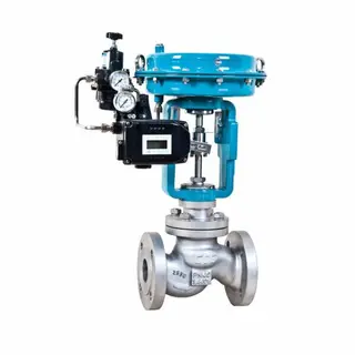
Globe valves are among the most common control valves due to their excellent throttling capability and precise flow regulation.
Features include:
- Accurate flow control
- High pressure capability
- Good shutoff performance
- Wide range of trim options
They are widely used in steam, chemical, and process industries.
Ball Control Valves
Ball valves use a rotating ball with a bore to regulate flow.
Advantages include:
- Low pressure drop
- Fast operation
- Tight shutoff
- Compact structure
Ball control valves are suitable for on-off and modulating applications.
Butterfly Control Valves
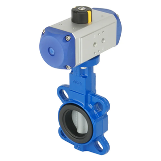
Butterfly valves use a rotating disc to control flow.
Benefits include:
- Lightweight design
- Large diameter capability
- Cost efficiency
- Fast operation
They are widely used in water treatment, HVAC, and low-pressure applications.
Diaphragm Valves
Diaphragm valves isolate the process medium from moving components using a flexible diaphragm.
These valves are ideal for:
- Corrosive fluids
- Slurries
- Sanitary applications
Plug Valves
Plug valves use a rotating plug to regulate flow.
They offer:
- Simple construction
- Reliable sealing
- Good resistance to dirty media
Applications of Pneumatic Control Valves
Pneumatic control valves are used across virtually every industrial sector.
Oil and Gas Industry
In oil and gas facilities, pneumatic control valves regulate:
- Crude oil flow
- Natural gas distribution
- Steam injection
- Pressure balancing
- Refining processes
Their explosion-proof operation makes them highly suitable for hazardous environments.
Chemical Processing
Chemical plants rely on pneumatic valves for precise control of:
- Reactive chemicals
- Corrosive media
- Temperature-sensitive processes
- Batch operations
Special alloy materials are often required for chemical resistance.
Power Generation
Power plants use pneumatic control valves to manage:
- Steam flow
- Boiler feedwater
- Turbine bypass systems
- Condensate systems
High-temperature and high-pressure service conditions require durable valve designs.
Water Treatment
Water facilities use pneumatic valves for:
- Filtration systems
- Chemical dosing
- Sludge handling
- Flow regulation
Butterfly and diaphragm valves are especially common.
Food and Beverage Industry
Sanitary pneumatic valves support:
- Hygienic fluid transfer
- CIP systems
- Beverage processing
- Dairy production
Stainless steel construction is typically required.
Pharmaceutical Manufacturing
Pharmaceutical facilities use pneumatic valves in sterile and contamination-sensitive applications requiring precise process control and sanitary operation.
Advantages of Pneumatic Control Valves
Pneumatic control valves offer numerous operational and economic benefits.
High Reliability
Compressed air systems are simple and dependable. Pneumatic actuators can operate continuously under harsh industrial conditions with minimal failure risk.
Fast Response
Pneumatic actuators respond quickly to control signals, enabling rapid process adjustments and stable control performance.
Intrinsic Safety
Because they do not depend on electrical power at the actuator, pneumatic valves are suitable for explosive and flammable environments.
Cost-Effective Operation
Compressed air is widely available in industrial facilities, reducing infrastructure costs.
Durable Construction
Pneumatic actuators tolerate vibration, temperature changes, and harsh environments better than many electric actuators.
Simple Maintenance
Most pneumatic systems feature straightforward mechanical designs that simplify maintenance and troubleshooting.
Challenges in Pneumatic Control Valve Operation
Despite their advantages, pneumatic control valves can experience operational problems under demanding process conditions.
Common issues include:
- Noise
- Cavitation
- Vibration
- Erosion
- Air leakage
- Stem wear
- Hysteresis
- Positioning instability
Proper valve selection, installation, and maintenance are essential for minimizing these problems.
Noise Problems in Pneumatic Control Valves
Noise is one of the most common issues associated with control valves, particularly in high-pressure applications.
Excessive valve noise can lead to:
- Worker discomfort
- Equipment damage
- Vibration problems
- Reduced valve life
- Safety concerns
Several factors contribute to valve noise generation.
Mechanical Vibration
Mechanical vibration occurs when internal valve components oscillate during operation.
For example:
- Valve plugs may vibrate within cages or sleeves.
- Stem movement may create resonance.
- Loose components may produce rattling sounds.
To reduce mechanical vibration:
- Minimize clearance between valve plug and sleeve
- Use hardened trim materials
- Improve valve guiding structures
- Increase component rigidity
Fluid Dynamic Noise
Fluid flowing through the valve creates turbulence, especially at high velocities or large pressure drops.
This turbulence generates aerodynamic or hydrodynamic noise.
Possible solutions include:
- Multi-stage trim designs
- Noise-reducing cages
- Pressure drop distribution
- Larger valve sizing
Natural Frequency Vibration
Every mechanical component has a natural vibration frequency.
If process conditions create excitation forces near this frequency, resonance can occur.
This may affect:
- Valve stems
- Plugs
- Actuator components
- Piping systems
Solutions may include:
- Changing trim geometry
- Modifying material properties
- Replacing components
- Reinforcing structural supports
Spool Instability
Valve spool instability can cause pressure fluctuations and oscillation.
This often results from:
- Improper tuning
- Low damping
- Excessive gain
- Flow-induced instability
Corrective measures include:
- Re-adjusting damping coefficients
- Adding damping mechanisms
- Improving actuator stability
- Optimizing control loop tuning
Cavitation in Pneumatic Control Valves
Cavitation is a serious issue in liquid control applications.
It occurs when liquid pressure falls below vapor pressure, forming vapor bubbles that collapse violently downstream.
Cavitation can cause:
- Severe erosion
- Noise
- Vibration
- Trim damage
- Reduced service life
Causes of Cavitation
Common causes include:
- High pressure drops
- Excessive flow velocity
- Improper valve sizing
- Poor trim design
Effects of Cavitation
Bubble collapse creates intense shock waves that damage valve surfaces.
Affected components may include:
- Valve seats
- Plugs
- Cages
- Body walls
Over time, cavitation can destroy internal trim components.
Preventing Cavitation
Several methods help reduce cavitation risk:
- Multi-stage pressure reduction
- Anti-cavitation trim
- Proper valve sizing
- Pressure recovery control
- Reduced operating pressure differential
Engineers often use specialized valve trims specifically designed for severe-service conditions.
Maintenance of Pneumatic Control Valves
Regular maintenance is essential for ensuring reliable valve performance and long service life.
Routine Inspection
Technicians should regularly inspect:
- Air supply quality
- Stem movement
- Packing leakage
- Positioner calibration
- Actuator response
Lubrication
Moving parts require proper lubrication to reduce wear and friction.
Air System Maintenance
Compressed air must remain:
- Clean
- Dry
- Oil-free
Moisture or contamination may damage internal pneumatic components.
Calibration
Periodic calibration ensures accurate valve positioning and control performance.
Trim Replacement
Valve trim components may eventually require replacement due to erosion, corrosion, or wear.
Smart Pneumatic Control Valve Technology
Modern industrial automation has introduced intelligent pneumatic control valves equipped with digital technologies.
Smart valves may include:
- Digital positioners
- Remote diagnostics
- Predictive maintenance
- Self-calibration
- Fieldbus communication
These advanced features improve plant efficiency, reduce downtime, and support Industry 4.0 integration.
Smart valve systems can continuously monitor:
- Valve travel
- Friction
- Air consumption
- Cycle count
- Operating conditions
This information helps maintenance teams detect problems before failures occur.
Selection Considerations for Pneumatic Control Valves
Choosing the correct pneumatic control valve requires careful evaluation of process conditions.
Important selection factors include:
Fluid Characteristics
- Engineers must consider:
- Liquid or gas
- Corrosiveness
- Viscosity
- Solids content
- Temperature
Pressure and Temperature
Valve materials and pressure ratings must match operating conditions.
Flow Requirements
Proper valve sizing ensures stable control and prevents excessive pressure drop.
Shutoff Requirements
Some applications require tight shutoff performance to prevent leakage.
Control Accuracy
Precision applications may require high-performance positioners and advanced trim designs.
Environmental Conditions
Outdoor or hazardous environments may require corrosion-resistant materials and explosion-proof accessories.
Future Development of Pneumatic Control Valves
Although pneumatic control valves have been used for decades, technological improvements continue to enhance their capabilities.
Current development trends include:
- Improved energy efficiency
- Advanced digital diagnostics
- Enhanced cavitation resistance
- Lower noise trim designs
- Better corrosion resistance
- Intelligent automation integration
- Reduced maintenance requirements
Manufacturers are also developing environmentally friendly solutions that minimize compressed air consumption and improve sustainability.
Conclusion
Pneumatic control valves remain one of the most essential components in modern industrial automation systems. Their ability to provide accurate, reliable, and safe flow regulation makes them indispensable across industries including oil and gas, power generation, water treatment, chemical processing, food production, pharmaceuticals, and manufacturing.
By using compressed air as the driving force, pneumatic control valves deliver fast response, excellent reliability, intrinsic safety, and cost-effective operation. Their wide variety of designs, actuator types, and trim configurations allows them to meet the demanding requirements of countless industrial applications.
However, successful operation requires proper valve selection, correct installation, regular maintenance, and careful management of challenges such as noise, vibration, and cavitation. Advances in smart valve technology and digital automation are further improving performance, diagnostics, and operational efficiency.
As industrial systems continue to evolve toward greater automation, energy efficiency, and process optimization, pneumatic control valves will continue to play a critical role in ensuring stable, safe, and efficient industrial operations worldwide.
Send your message to this supplier
Related Articles from the Supplier
Related Articles from China Manufacturers
Understanding Pneumatic Ball Control Valves
- Jun 27, 2024
Understanding Pneumatic Control Valve Principles
- May 13, 2024
Related Products Mentioned in the Article

Supplier Website
Source: https://www.mfrsvalve.com/news/understanding-pneumatic-control-valves-key-components-and-operation-guide.html