Pneumatic Control Valve: Principle, Structure & Application
In industrial production, controlling flow, pressure, and temperature within piping systems is critical for ensuring both operational safety and product quality. Traditional manual valves require human intervention, which is not only inefficient but also makes precise adjustment difficult under complex operating conditions. With the advancement of industrial automation, pneumatic control valves have emerged as indispensable components of modern industrial control systems.
Pneumatic control valves utilize compressed air as a power source, working in conjunction with control systems to automatically regulate valve opening and flow. They are widely used in industries such as chemical processing, petroleum, power generation, and water treatment. Whether controlling temperature and pressure within reaction vessels or regulating water pressure in urban distribution networks, pneumatic control valves provide reliable and stable solutions. This article offers a detailed overview of pneumatic control valves, covering their basic concepts, structural components, working principles, applications, selection criteria, as well as installation and maintenance practices, providing readers with a comprehensive understanding of this critical industrial control equipment.
What is a Pneumatic Control Valve?
A pneumatic control valve is an industrial automation device that uses compressed air as its power source. It drives the valve to open, close, or partially open via a pneumatic actuator, enabling precise regulation of flow, pressure, or temperature in pipelines. Unlike manually operated valves, pneumatic control valves receive signals from a control system and automatically perform valve adjustments, ensuring continuous control of fluid parameters.
During industrial operations, the control system collects real-time data from sensors, calculates the required valve position, and transmits a signal to the pneumatic control valve. Upon receiving this signal, the valve converts the air pressure into mechanical force to move the valve stem, changing the flow area between the valve plug and seat, thus regulating fluid flow. This automated control method significantly improves production efficiency while maintaining stability and accuracy of process parameters.
Pneumatic control valves are widely applied across petrochemical, chemical, power generation, metallurgy, pharmaceutical, and food industries. For instance, they are used to regulate temperature and pressure in chemical reactors, maintain stable water pressure in municipal supply networks, and control steam flow in heating systems. Because they are powered by compressed air rather than electricity, pneumatic control valves are inherently safe in flammable or explosive environments and do not require additional explosion-proof measures.
Structure of Pneumatic Control Valves
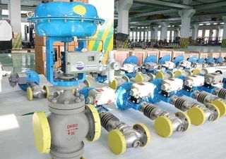
A pneumatic control valve is mainly composed of three parts: the pneumatic actuator, the valve body, and accessories.
1. Pneumatic Actuator
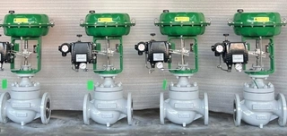
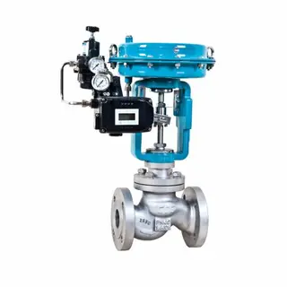
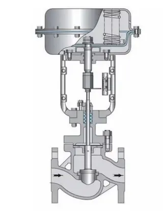
The pneumatic actuator serves as the power source of the valve, converting air pressure signals into mechanical force to operate the valve. Depending on structure and operation, actuators are primarily categorized into diaphragm-type and piston-type.
Diaphragm Actuators consist of a flexible circular diaphragm, a spring, a push rod, and the valve stem. When compressed air enters the diaphragm chamber, air pressure causes the diaphragm to expand, pushing the rod and valve stem to change the valve opening. When air pressure decreases or disappears, the spring returns the valve stem to its initial position. Diaphragm actuators are simple in structure, respond quickly, and are suitable for small- to medium-diameter valves with low pressure differentials.
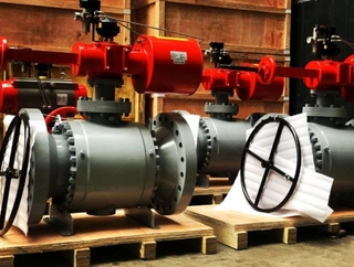
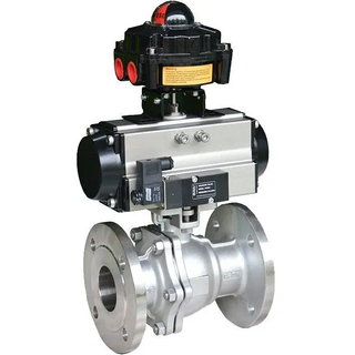
Piston Actuators are structurally similar to a cylinder, with a piston moving inside the cylinder and the valve stem connected to it. When compressed air drives the piston, it moves the valve stem to open or close the valve. Piston actuators can be single-acting or double-acting. Single-acting actuators use air pressure for one movement cycle and rely on the spring for the return stroke, while double-acting actuators use air pressure for both opening and closing strokes, independent of springs. Piston actuators offer longer travel and higher thrust than diaphragm actuators, making them suitable for large-diameter valves, high-pressure applications, or situations requiring significant force.
2. Valve Body
The valve body is the part directly in contact with the medium and where actual flow control occurs. Internally, it contains critical components such as the valve plug and seat.
Valve bodies are typically of the two-way type, which can be installed in-line or at a 90-degree angle (angle-type valves). Angle-type valves are preferred for horizontal pipeline installations to prevent residue accumulation, blockage, or corrosion in unused valves. Valve bodies are usually made from durable and heat-resistant alloys, including cast iron, stainless steel, and carbon steel. Stainless steel is suitable for corrosive media, while cast iron fits general service conditions.
The valve plug directly controls the fluid flow and pressure by adjusting the flow area in coordination with the seat. Common plug designs include straight-through, angle, spherical, and piston types. The valve seat forms a sealing surface with the plug to prevent fluid flow when closed, typically made from wear-resistant and corrosion-resistant materials.
3. Accessories
Pneumatic control valve accessories include valve positioners, solenoid valves, filters, and pressure regulators.
Valve positioners are critical for precise control. They use a force-balance principle to position the valve plug accurately according to the control signal. The positioner converts the control signal into the required actuator air pressure and monitors the valve stem position via feedback, adjusting output until the actual position matches the setpoint. This mechanism overcomes friction and unbalanced forces from the medium, greatly enhancing accuracy and response speed.
Solenoid valves control the entry of compressed air into the actuator for remote valve operation. Filters and pressure regulators clean and stabilize the air supply, ensuring clean, stable compressed air reaches the actuator.
Working Principle of Pneumatic Control Valves
The operation of a pneumatic control valve can be divided into three stages: signal reception and conversion, actuator movement, and valve position feedback and adjustment.
1. Signal Reception and Conversion
The control system calculates the required valve opening and sends a control signal to the valve. Signals can be pneumatic or electronic (e.g., 4–20 mA). For electronic signals, an electro-pneumatic positioner converts them into air pressure signals that the actuator can recognize and respond to.
A typical signal-to-position relationship is: 4 mA = fully closed (0% open), 20 mA = fully open (100% open), with intermediate values corresponding proportionally.
2. Actuator Movement
When the air signal reaches the actuator, it generates force on the diaphragm or piston. This force must overcome spring resistance, valve stem friction, and unbalanced forces from the fluid to move the valve.
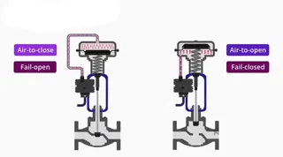
Air-to-open valves gradually open as air pressure increases and close as it decreases, fully closing without pressure. They are used where medium shutdown is required during air failure, such as fuel gas pipelines.
Air-to-close valves gradually close as air pressure increases and open as it decreases, fully opening without pressure. They are suitable for systems that must maintain flow during air failure, like cooling water lines.
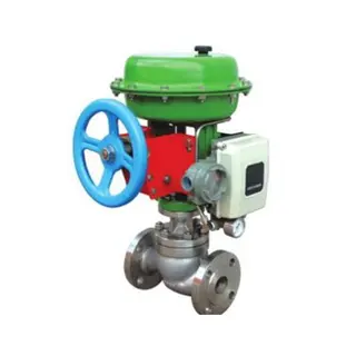
Single-acting actuators rely on an internal spring to return the valve to a safe position if air fails, whereas double-acting actuators hold the valve in place.
3. Valve Position Feedback and Adjustment
During operation, the positioner continuously monitors the valve stem and compares it with the target. Any deviation triggers automatic air pressure adjustments to bring the stem to the desired position. This closed-loop feedback occurs continuously, allowing rapid correction of disturbances. Well-calibrated pneumatic control valves can achieve ±0.5% to ±1% full-scale position accuracy.
Applications of Pneumatic Control Valves
Pneumatic control valves, with fast response, high thrust, inherent safety, and robustness, are widely applied across industries. Below are their applications in four major sectors:
1. Chemical and Pharmaceutical Industry
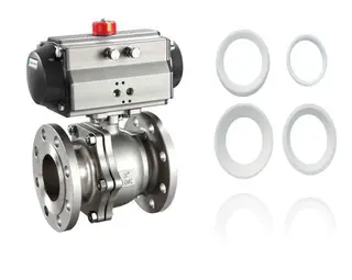
In chemical and pharmaceutical processes, pneumatic control valves regulate corrosive fluids or gases, ensuring stable reaction temperatures, pressures, and material ratios. Valve bodies are often stainless steel, while seats and seals use PTFE, EPDM, or other chemically resistant materials.
2. Oil and Gas Industry
In oil and gas pipelines, pneumatic control valves precisely regulate flow and pressure, ensuring safe and efficient transport. Their inherent safety makes them ideal for flammable media. In gas pressure-regulating stations, the valves adjust openings based on downstream pressure to maintain stable supply.
3. Power and Energy Industry
In thermal power plants, pneumatic valves control boiler feedwater, steam flow, and combustion systems to maintain safe and stable operation. In heating systems, they regulate hot water or steam flow to control temperature.
4. Water Treatment and Environmental Protection
In municipal water supply, pneumatic control valves regulate network flow and maintain stable pressure. In wastewater treatment, they control chemical dosing for effective treatment. In cooling water systems, they adjust flow to conserve energy.
Selection Criteria for Pneumatic Control Valves
Due to the wide variety of valves and operating conditions, proper selection is crucial to ensure reliable operation, longevity, and safety.
1. Determine Fail-Safe Position
Consider process safety: should the valve fail closed or open upon air or signal loss? For fuel pipelines, air-to-open valves (fail-closed) are preferred, while cooling water lines require air-to-close (fail-open) valves.
2. Choose Valve Body Material
Select material based on medium properties, temperature, and pressure. Stainless steel suits corrosive media; carbon steel suits general service; cast iron is suitable for low-pressure, ambient temperature; alloy or special steel may be needed for high temperature and pressure.
3. Select Actuator Type
Single-acting actuators are suitable for emergency cut-off scenarios, while double-acting actuators suit frequent adjustments. Piston actuators are recommended for large-diameter or high-pressure valves; diaphragm actuators suffice for small-diameter, low-pressure valves.
4. Determine Key Parameters
Confirm medium type, flow range, accuracy, operating temperature and pressure, pipe size, connection method, and response requirements. Flow capacity should match maximum flow and allowable pressure drop; undersizing limits flow, oversizing reduces accuracy.
Installation and Maintenance
- Installation Notes: Ensure the valve is centered in the pipeline to prevent leakage. Provide sufficient straight pipe sections upstream and downstream for stable flow. Install filters and dryers in the air supply to prevent corrosion or freezing. For high-temperature pipelines, insulate actuators to prevent seal aging.
- Routine Maintenance: Check air supply stability, clean debris from valve stem and seat, inspect packing seals, and verify positioner calibration. Inspect wear on valve plug and seat periodically and replace worn seals.
- Troubleshooting: If the actuator fails, check air supply and signal integrity. Slow valve movement may indicate insufficient air pressure, clogged filters, or excessive friction. Inaccurate positioning may stem from positioner calibration issues or loose feedback. Leakage usually results from aged seals or damaged plug/seat.
Conclusion
As a key actuator in industrial automation, pneumatic control valves achieve precise regulation of flow, pressure, and temperature using compressed air. They consist of the actuator, valve body, and accessories, with operation based on closed-loop force conversion. Their fast response, high thrust, and inherent safety make them ideal for chemical, petroleum, power, and water treatment applications. Proper selection, installation, and maintenance ensure long service life and stable, safe system operation.
Send your message to this supplier
Related Articles from the Supplier


Related Articles from China Manufacturers

Understanding Pneumatic Control Valve Principles
- May 13, 2024
.jpg)
Installation Principles of Pneumatic Control Valves
- Mar 31, 2022
Installation Principles of Pneumatic Control Valves
- Feb 12, 2022

Pneumatic Control Valve: Air Open and Air Close
- Jul 10, 2024
Related Products Mentioned in the Article
Supplier Website
Source: https://www.magpievalves.com/media-hub/pneumatic-control-valve-principle-structure-application.html