Pneumatic Ball Valve Fault Diagnosis and Maintenance Guide
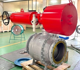
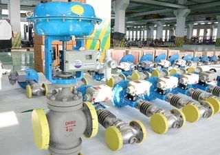
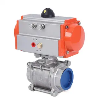
In modern industrial production, pneumatic ball valves can truly be described as the ubiquitous air stewards of piping systems. From petrochemical and power generation industries to food processing, pharmaceuticals, and water treatment, these valves, driven by compressed air, play a critical role in controlling fluid on/off operations. Simply put, a pneumatic ball valve is an automated valve that uses compressed air as its power source, driving a pneumatic actuator to rotate the ball and open or close the pipeline.
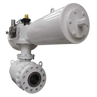
Its core advantages lie in its simple structure, fast response, and high safety and reliability. Pneumatic actuation is especially suitable for flammable and explosive environments, as it fundamentally eliminates the risk of electrical sparks associated with electric actuators. However, like all mechanical equipment, pneumatic ball valves inevitably experience faults during long-term operation, with air leakage being the most common issue.
This article provides an in-depth explanation of the working principles of pneumatic ball valves, systematically outlines diagnostic methods for common faults, and offers practical maintenance recommendations to help users quickly locate problems and resolve failures efficiently.
Fundamentals of the Pneumatic System
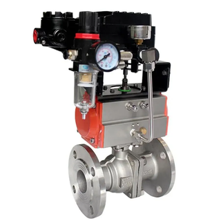
To understand why pneumatic ball valves develop various faults, it is essential to first understand how their power system works. Although a pneumatic ball valve appears externally as a simple metal assembly, its internal operation relies on a precise pneumatic control system to complete each opening and closing action. Much like the human respiratory system, it requires a stable, clean, and appropriately pressurized air supply, as well as responsive neural signals to transmit commands.
This section breaks down the operating fundamentals of pneumatic ball valves from two perspectives: air supply treatment and control signal systems.
1. Air Preparation Unit
For proper operation, a pneumatic ball valve requires a healthy air supply system, typically consisting of three key components collectively known as the air preparation unit:
- Filter: Removes moisture, oil, and solid particles from compressed air, acting like a mask for the valve
- Pressure Regulator: Reduces and stabilizes the supply pressure to a suitable working range, functioning as the valve's voltage stabilizer
- Lubricator: Atomizes lubricating oil into the air stream to lubricate internal cylinder components, serving as the valve's nutrient supply
During routine inspections, first check whether the pressure gauge reading is within the normal range of 3–8 kg/cm² (0.3–0.8 MPa). Insufficient pressure can cause weak actuation and incomplete closure, while excessive pressure may damage seals and accelerate air leakage. Additionally, regularly drain accumulated water from the filter bowl and verify that the lubricator's oil drip rate is normal.
2. Control Signal System
The signal system of a pneumatic ball valve consists of two sets of circuits:
- Control signal lines (input): Receive command signals from the PLC (Programmable Logic Controller)
- Feedback signal lines (output): Transmit the actual valve position back to the control system
The operating sequence is as follows: when the PLC issues an open or close command, the signal is sent to a positioner (for control valves) or a solenoid valve (for on/off valves). The positioner converts the electrical signal into a pneumatic pressure signal, regulating air pressure to drive the valve stem. Meanwhile, the valve stem position is continuously fed back to the control system, forming a closed-loop control.
Important note: If the control system display does not match the actual valve position, or if there is no feedback signal at all, use a multimeter to check the wiring:
- Verify voltage at each terminal
- Confirm correct wiring with no missing or incorrect connections
- Inspect cable insulation for damage and internal conductor breakage
- Check that terminals are tight and making good contact
Air Leakage Fault Diagnosis
Air leakage is the most common fault in pneumatic ball valves, but it is merely a symptom. The underlying causes can vary widely. Like a physician diagnosing an illness, we must identify the root cause based on the leakage location.
1. Air Leakage from Cylinder Exhaust Ports
- Symptom: Continuous air discharge from the exhaust silencers at both ends of the cylinder, even when the valve is stationary.
- Cause analysis: This typically indicates aging or wear of internal piston seals. Inside the actuator, pistons (or yokes in scotch-yoke designs) rely on sealing rings to separate chambers. After long-term reciprocating motion, these seals may harden, wear, or lose elasticity, allowing compressed air to leak from one chamber to the other and exit through the exhaust ports.
- Solution: Replace the internal cylinder seal set. It is recommended to contact the manufacturer or qualified service personnel, as actuator disassembly requires special tools and internal springs may be preloaded, posing safety risks if handled improperly.
2. Air Leakage at Cylinder End Caps
- Symptom: Air leakage at the junction between the cylinder body and the end caps.
- Cause analysis: This is usually caused by failure of the end-cap seals. Frequent actuator movement leads to long-term compression and deformation of O-rings or gaskets, compromising sealing performance. Loose fastening bolts may also create sealing gaps.
- Solution: First, evenly tighten the end-cap bolts in a cross pattern to avoid misalignment. If leakage persists, disassemble the cylinder and replace the end-cap seals.
3. Air Leakage at the Valve Stem Interface
- Symptom: Air leakage from the point where the valve stem exits the actuator.
- Cause analysis: This indicates failure of the packing seal. The valve stem undergoes rotational motion at this location, and the packing must both seal effectively and allow smooth rotation. Long-term friction causes wear, while excessive torque from valve sticking can accelerate damage.
- Solution: If the design permits, tighten the packing gland bolts slightly. If ineffective, replace the packing material, ensuring compatibility with the process medium (e.g., corrosion resistance or high-temperature capability).
4. Solenoid Valve Air Leakage
- Symptom: Air leakage from the solenoid valve body or fittings.
- Cause analysis: A common cause is excessive regulated pressure exceeding the solenoid valve's rated operating pressure, leading to seal failure. Alternatively, internal seals may be damaged or contaminants may prevent the valve spool from fully resetting.
- Solution: First, check and adjust the pressure regulator to within the normal range (3–8 kg/cm²). If leakage persists, clean or replace the solenoid valve.
5. Air Leakage Due to Broken Cylinder Springs
- Symptom: Weak actuator movement accompanied by abnormal air leakage noise.
- Cause analysis: If the return springs inside the actuator break or fatigue, the piston or yoke cannot reach its designed position, causing seals to operate outside their normal range and resulting in leakage.
- Solution: Replace the spring assembly. This usually requires complete actuator disassembly and should be performed by qualified personnel.
Abnormal Actuation Faults
Resolving air leakage does not guarantee normal valve operation. In practice, valves may still exhibit abnormal behavior: failing to close tightly, not opening, or moving slowly despite normal air pressure and intact piping. These faults are often more subtle and disruptive to production.
1. Failure to Fully Close (Zero Position Not Reached)
This common issue can arise from two very different scenarios:
- Scenario 1: Valve is mechanically closed, but signal indicates otherwise
- Diagnosis: If on-site inspection confirms the ball has rotated 90° to the closed position while the control system shows partial opening, the issue is signal-related.
- Solution: Adjust the positioner or limit switches. For mechanical limit switches, reposition the cams; for positioners, recalibrate the zero point.
- Scenario 2: Valve is not fully closed and media continues to leak
- Possible causes:
- Seat seal damage: Wear, deformation, or aging of seat seals due to abrasive particles or corrosive media
- Valve stem binding: Insufficient lubrication or crystallization and scaling of the medium increase torque beyond actuator capacity
- Solutions:
- Disassemble the valve and replace seat seals through the manufacturer
- Lubricate rotating components
- Evaluate media properties and improve process conditions or valve material selection if necessary
2. Valve Cannot Open or Operates Slowly
- Insufficient air pressure: Check compressor operation, network pressure, and whether other air-consuming equipment causes pressure drops
- Blocked or leaking air lines: Inspect hoses for kinks or deformation, fittings for leaks, and flow control valves for overly restricted settings
- Poor lubrication: Verify lubricator operation; add grease through actuator lubrication ports if necessary
- Valve sticking: Foreign matter, scaling, or corrosion may lock the ball. Avoid forced operation; attempt manual turning and disassemble for cleaning if needed
3. Actuator Moves but Valve Stem Does Not Rotate
This indicates failure of mechanical connection components:
- Broken coupling pins: Pins or keys transmitting torque between actuator and stem may shear under long-term impact loads
- Worn keyways: Enlarged keyways cause slippage
- Broken valve stem: The most severe case, typically due to prolonged actuator torque against a stuck valve
- Corrective action: Disassemble the actuator, inspect all connection components, and replace damaged pins, keys, or valve stems.
Control and Signal Faults
If the air supply and actuator are the valve's muscles, the control system is its brain. Many failures occur not because of mechanical issues, but due to signal transmission or control logic problems, leading to discrepancies between field conditions and control room displays.
1. Valve Position Feedback Does Not Match Actual Position
- Limit switch misalignment: Adjust cam positions to ensure accurate triggering at fully open and fully closed positions
- Positioner malfunction (control valves): Zero drift, nozzle–flapper blockage, or diaphragm damage may cause inaccurate control; recalibrate or replace if necessary
- Feedback circuit faults: Check terminals for looseness, wiring for damage or short circuits, and feedback resistors or potentiometers for failure
2. Frequent Valve Oscillation (Hunting at Small Openings)
This is particularly troublesome in control valves and may be caused by:
- Excessive positioner sensitivity: Reduce gain settings
- Improper PID parameters: Proportional band too small or integral time too short
- Fluctuating air supply pressure: Improve compressor stability or increase air storage capacity
- Insufficient actuator rigidity: Reinforce mounting or select a larger actuator
Conclusion
Although pneumatic ball valves have relatively simple structures, their reliable operation depends on the coordinated performance of four systems: air supply, control, actuation, and the valve body itself. Air leakage and abnormal actuation are the most common faults, but by following a systematic troubleshooting logic, air supply first, then signals, followed by the actuator, and finally the valve body, most issues can be resolved efficiently. Preventive maintenance is always more cost-effective than corrective repairs. Regular inspection of air quality, proper lubrication, timely replacement of aging seals, and maintaining comprehensive maintenance records are essential for ensuring long-term stable operation of industrial systems. When faced with complex or uncertain faults, avoid blind disassembly. Instead, consult the valve manufacturer or professional service personnel. Improper repairs may worsen the problem, void warranties, or even introduce safety risks. It is hoped that this guide will serve as a practical on-site reference, ensuring every pneumatic ball valve breathes smoothly and operates with precision, safeguarding reliable industrial production.
Send your message to this supplier
Related Articles from the Supplier

Related Articles from China Manufacturers
Related Products Mentioned in the Article
Supplier Website
Source: https://www.magpievalves.com/media-hub/pneumatic-ball-valve-fault-diagnosis-and-maintenance-guide.html