An Introduction to Hydraulic Counterweight Butterfly Valve
Hydraulic counterweight butterfly valves are widely used in modern industrial systems where precise flow regulation, stable operation, and high reliability are essential. By integrating a hydraulic actuation system with a mechanical counterweight mechanism, this type of valve achieves a balance between control accuracy and operational stability, making it particularly suitable for large-diameter and high-pressure pipeline systems.
This article provides a comprehensive and structured overview of hydraulic counterweight butterfly valves, including their structure, working principles, application scenarios, advantages, limitations, and maintenance considerations.
Structure of Hydraulic Counterweight Butterfly Valve
A hydraulic counterweight butterfly valve is composed of five primary components: the valve body, disc, valve stem, hydraulic actuator, and counterweight mechanism. Each part plays a critical role in ensuring efficient and reliable valve operation.
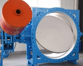
1. Valve Body
The valve body serves as the main pressure-bearing component and is installed directly within the pipeline. It is typically made of carbon steel, stainless steel, or alloy materials, depending on the application requirements. The design of the valve body ensures sufficient strength to withstand internal pressure, temperature variations, and external loads.
2. Disc
The disc is the core flow control element of the valve. It is mounted within the valve body and rotates to regulate or stop fluid flow. When the disc is parallel to the flow direction, the valve is fully open; when it is perpendicular, the valve is fully closed. Intermediate positions allow for throttling and flow control.
3. Valve Stem
The valve stem connects the disc to the actuator. It transmits torque generated by the hydraulic actuator to the disc, enabling rotation. The stem must possess high strength and corrosion resistance, as it is subjected to both mechanical stress and fluid exposure.
4. Hydraulic Actuator
The hydraulic actuator is the power source of the valve. It converts hydraulic energy into mechanical motion, driving the valve stem and disc. Common actuator types include piston-type actuators with crank-link or rack-and-pinion mechanisms. The actuator is typically connected to a hydraulic power unit that supplies pressurized oil.
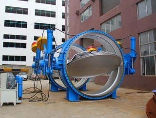
5. Counterweight Mechanism
The counterweight mechanism is a distinguishing feature of this valve type. It is installed at the extended end of the valve stem and consists of a weight block, lever arm, and support structure. The counterweight generates a gravitational torque that offsets the torque caused by fluid pressure acting on the disc.
By balancing these opposing forces, the counterweight reduces the load on the hydraulic actuator and improves the stability of valve operation.
Hydraulic Counterweight Butterfly Valve Working Principle
The hydraulic counterweight butterfly valve operates through the coordinated action of hydraulic driving and mechanical balancing. Its working principle can be divided into three key aspects: hydraulic actuation, counterweight balancing, and sealing performance.
1. Hydraulic Actuation System
When a control signal is sent from the control system (such as a PLC or DCS), the hydraulic power unit delivers pressurized oil to the actuator cylinder. The oil pushes the piston, generating linear motion.
This linear motion is then converted into rotational motion through a mechanical transmission mechanism (such as a crank-link system or rack-and-pinion gear). The rotation of the valve stem drives the disc to move between 0° and 90°, thereby controlling the flow.
One of the major advantages of hydraulic systems is their ability to provide precise and continuous control. By adjusting the oil pressure and flow rate, the operator can accurately control the speed and position of the disc. With the use of proportional or servo valves, the system can achieve stepless regulation, allowing the valve to operate at any desired opening angle.
2. Counterweight Balancing Mechanism
In pipeline systems, especially those with large diameters or high flow velocities, the disc is subjected to significant fluid forces. These forces generate torque that may either assist or resist valve movement, depending on the flow direction and installation orientation.
Without a counterweight, the actuator must overcome this unbalanced torque, which increases energy consumption and reduces control precision.
The counterweight mechanism addresses this issue by introducing a balancing torque. The weight block, positioned at a certain distance from the stem axis, generates a gravitational moment that opposes the fluid-induced torque.
By carefully selecting the mass and position of the counterweight, engineers can achieve near-equilibrium conditions over a wide range of operating angles. This results in smoother operation, reduced actuator load, and improved energy efficiency.
Additionally, in the event of hydraulic system failure, the counterweight provides a passive safety function. It can hold the valve in position or allow it to move slowly to a predefined safe position, minimizing the risk of sudden pressure changes and water hammer.
3. Sealing Mechanism
Sealing is a critical aspect of valve performance. Hydraulic counterweight butterfly valves typically use either metal or soft sealing systems:
Metal sealing: Suitable for high-temperature, high-pressure, and corrosive environments. The sealing surfaces are precision-machined metal components that achieve tight sealing through direct contact.
Soft sealing: Typically uses elastomer materials such as rubber or PTFE. It is suitable for low-pressure and moderate-temperature applications, offering excellent sealing performance with low leakage.
The presence of the counterweight reduces the torque required to press the sealing surfaces together, thereby minimizing wear and extending service life.
Hydraulic Counterweight Butterfly Valve Applications
Hydraulic counterweight butterfly valves are widely used across various industries due to their versatility and reliability.
1. Water Treatment Industry
In water supply systems, these valves regulate flow based on real-time demand, ensuring balanced distribution across treatment units. In wastewater treatment plants, they are used in processes such as sludge return, aeration control, and discharge regulation.
Large pipeline diameters in these systems make hydraulic actuation particularly advantageous.
2. Power Generation
In thermal and nuclear power plants, the valves control cooling water flow, ensuring optimal operating conditions for turbines and condensers. In hydropower stations, they are used in high-pressure pipelines, where stable operation is critical.
The counterweight mechanism helps balance hydraulic forces, ensuring safe and smooth operation under extreme conditions.
3. Oil and Gas Industry
These valves are commonly used in pipeline isolation, compressor stations, and refinery processes. They provide reliable shut-off and precise flow control, even under high-pressure and high-flow conditions.
Integration with control systems allows automated operation, improving efficiency and safety.
4. Fire Protection Systems
In fire protection networks, hydraulic counterweight butterfly valves enable rapid response to emergency signals. They ensure smooth opening, reducing the risk of water hammer and ensuring reliable water supply during firefighting operations.
5. HVAC Systems
In heating, ventilation, and air conditioning systems, these valves regulate water flow in chillers, cooling towers, and distribution networks. Their precise control capability ensures efficient energy use and stable indoor conditions.
6. Chemical Industry
In chemical processing plants, these valves handle corrosive and hazardous fluids. They are used in reactors, storage tanks, and transport pipelines, where precise flow control is essential for process safety and efficiency.
Key Advantages of Hydraulic Counterweight Butterfly Valve
- High Control Accuracy: Hydraulic systems allow precise adjustment of pressure and flow, enabling accurate positioning of the valve. This makes them ideal for applications requiring fine control of fluid flow.
- Smooth Operation: The counterweight ensures balanced movement, preventing sudden changes in speed. This reduces mechanical stress and enhances system stability.
- Reduced Water Hammer Risk: By slowing down the closing process, the valve minimizes pressure surges, protecting pipelines and equipment.
- Wide Operating Range: These valves can handle a wide range of sizes, pressures, temperatures, and media types, making them highly versatile.
- Compact Design: Compared to other valve types, butterfly valves have a shorter face-to-face length, saving installation space.
- Long Service Life: With proper maintenance, hydraulic counterweight butterfly valves can operate reliably for decades.
Hydraulic Counterweight Butterfly Valve Limitations
- Dependence on Hydraulic Systems: A stable hydraulic power source is essential. Backup systems are recommended for critical applications.
- Maintenance Requirements: Regular maintenance of the hydraulic system, including oil replacement and filtration, is necessary to ensure reliable operation.
- Initial Cost: The initial investment is higher compared to simpler valve types, but lifecycle costs are often lower.
- Residual Water Hammer Risk: Although reduced, water hammer cannot be completely eliminated, and additional protective measures may be required.
Hydraulic Counterweight Butterfly Valve Selection
When selecting a hydraulic counterweight butterfly valve, engineers should consider:
- Pipeline diameter and pressure rating
- Fluid properties (temperature, corrosiveness, viscosity)
- Required control accuracy
- Installation environment and available space
- Reliability and safety requirements
Proper sizing of the actuator and counterweight is essential for optimal performance.
Hydraulic Counterweight Butterfly Valve Maintenance Practices
To ensure long-term performance:
- Regularly inspect hydraulic oil quality and replace as needed
- Clean or replace filters to maintain oil cleanliness
- Lubricate moving parts of the counterweight mechanism
- Check for corrosion and apply protective coatings
- Test valve operation periodically to ensure responsiveness
Conclusion
Hydraulic counterweight butterfly valves represent a highly efficient and reliable solution for flow control in demanding industrial applications. By combining hydraulic precision with mechanical balance, they provide superior performance in terms of control accuracy, operational stability, and durability.
Although they require higher initial investment and careful maintenance, their long service life and reduced operational risks make them a valuable choice for critical systems.
A thorough understanding of their structure, working principles, and application requirements enables engineers to make informed decisions and maximize the benefits of this advanced valve technology.
Send your message to this supplier
Related Articles from the Supplier
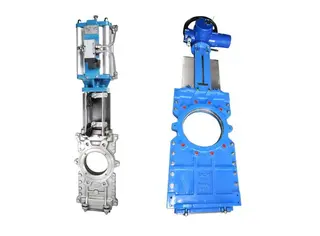
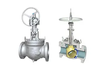
An Introduction to Through-Conduit Knife Gate Valve
- Sep 04, 2025
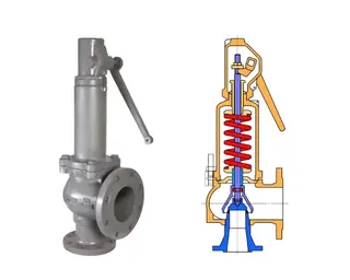
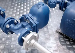
An Introduction to Full-Lift Safety Valve
- Sep 19, 2025
An Introduction to Orbit Ball Valve
- Nov 26, 2025
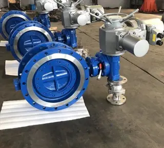
An Introduction to Metal-Seated Butterfly Valves
- Jan 07, 2026
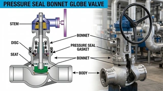
An Introduction to Pressure Seal Bonnet Globe Valve
- Mar 28, 2026
An Introduction to PTFE Lined Ball Valves
- Jun 01, 2026
Related Articles from China Manufacturers

An Introduction to the Digital Two Way Radios
- May 16, 2017
An Introduction to Heated Welding Ball Valves
- Aug 10, 2020
An Introduction to Stainless Steel Ball Valves
- Aug 20, 2020

An Introduction to 23mn Steel Pipe
- Aug 29, 2020
An Introduction to Coated Steel Pipes
- Jan 06, 2021
An Introduction to Flange Joints
- Aug 19, 2020

An Introduction to Vacuum Packaging for Food
- Mar 03, 2021
Related Products Mentioned in the Article
Zhejiang Kosen Valve Co., Ltd.
- https://www.kosenvalve.com/
- Business Type: Industry & Trading, Manufacturer,
Supplier Website
Source: https://www.kosenvalve.com/media-hub/an-introduction-to-hydraulic-counterweight-butterfly-valve.html