An Introduction to Alternators in Generator Sets
In a generator set, the alternator serves as the core component that converts mechanical energy into electrical energy. Its performance directly determines the quality and stability of the output power. Whether in factories, hospitals, or data centers, reliable electricity supply relies on an alternator perfectly matched to the engine. This article systematically introduces the working principles and selection considerations of alternators, covering frequency and voltage selection, insulation levels, excitation systems, harmonic handling, maintenance, and more, helping readers understand how this key device impacts the overall operational efficiency and reliability of a generator set.
The Core Role of Alternators in Generator Sets
To understand the value of an alternator within a generator set, it is essential first to clarify its core functions and positioning. The conversion of mechanical energy into electrical energy and the matching relationship between the alternator and the engine form the foundation for understanding this crucial device.
1. Conversion of Mechanical Energy to Electrical Energy
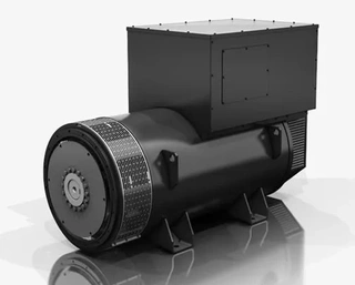
The alternator in a generator set is the key device that transforms mechanical energy into electrical energy. The engine generates mechanical energy during operation, and the alternator receives this energy and, through the principle of electromagnetic induction, converts it into electrical energy to supply the connected load. Many people assume that a diesel generator produces electricity solely because of the engine. In reality, the engine provides only mechanical energy; it is the alternator that converts this mechanical energy into stable alternating current.
An alternator is a rotating electromechanical device, consisting of a rotor, stator, excitation system, and automatic voltage regulator (AVR). The rotor generates a rotating magnetic field, excited by direct current, and rotates at a specific speed—typically 1,500 RPM for 50 Hz systems and 1,800 RPM for 60 Hz systems. The stator is a fixed three-phase winding that generates output voltage through electromagnetic induction. The excitation system is a coaxial small AC generator supplying DC to the rotor, with current transmitted through a rotating rectifier bridge. The AVR is an electronic controller that monitors output voltage in milliseconds and adjusts excitation to ensure voltage stability.
2. The Matching Relationship Between Alternator and Engine
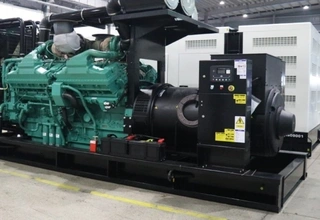
The alternator is the critical component of any power generation system and the device most closely matched with the engine. Selecting the appropriate alternator for a given application is essential, as not all alternators are identical. Only when the alternator and engine are perfectly matched can the ideal engine-alternator combination be achieved. The alternator ultimately determines voltage stability, short-circuit capacity, and starting kVA—not the engine alone. Therefore, during selection, ensuring compatibility between the engine and alternator is crucial to optimize performance, fuel efficiency, and load-handling capabilities.
Selection of Frequency, Voltage, and Connection Method
Once the basic role of the alternator is understood, attention should turn to the configuration of its electrical output parameters. Frequency selection, voltage level, connection method, and the number of winding leads are three fundamental factors that determine whether a generator meets application requirements. These are explained below.
1. Application Areas for 50 Hz and 60 Hz
The frequency of an alternator depends on the engine speed and number of poles, and the engine must be selected accordingly to ensure the generator’s electrical output meets local grid standards. The most common frequencies are 50 Hz and 60 Hz. Fifty hertz is widely used in Europe, most African countries, Australia, China, and parts of South America. Sixty hertz is used in the United States, Canada, and parts of Latin America. Within these frequencies, alternators can provide various voltage levels. The selected voltage impacts whether the generator is low-voltage or medium-to-high voltage, as well as the connection method.
2. Voltage Levels and Connection Methods
Common low-voltage three-phase connections include 400/230V 3F+N for 50 Hz and 480/277V, 440/254V, 380/220V, and 220/127V 3F+N for 60 Hz. The connection method of an alternator depends on the number of phases, configuration, and the number of winding leads. The phases can be single-phase, three-phase, or split-phase. In terms of configuration, star connections are used when a neutral point is available, while delta connections are used when no neutral point exists.
3. Number of Winding Leads and Flexibility
Alternator windings commonly have six or twelve leads. Six-lead windings can be reconnected between star and delta configurations, providing rated three-phase voltage. Twelve-lead windings allow single-phase, split-phase, and three-phase reconnections, enabling a wider range of rated voltages. Therefore, twelve-lead windings are the most common and flexible type, capable of adapting to diverse application requirements.
Environmental Factors and Protective Treatments
After meeting electrical parameters, consideration must be given to the external environmental conditions in which the alternator will operate. Major environmental threats, along with tropicalization and marine-grade treatments, are critical measures for ensuring reliable operation in harsh environments. These are discussed below.
1. Major Environmental Threats
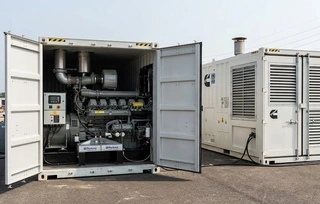
Key factors affecting alternator operation are often external environmental conditions. Altitude, extreme climates, and marine corrosion are the main threats. High-altitude areas have thinner air, reducing cooling efficiency and increasing the risk of overheating. Extreme climates—high temperatures, high humidity, salt spray—accelerate the aging of insulation materials and corrosion of metal components. Salt-laden marine environments are particularly damaging to windings and insulation.
2. Tropicalization and Marine Treatments
Various specialized protective treatments can prevent environmental damage. Tropicalization is designed for high-temperature, high-humidity conditions and protects windings and insulation through special coatings and sealing processes. Marine treatments are intended for high-corrosion environments, using anti-corrosion materials and processes to prevent rust, water damage, friction, and heat-related issues. Regardless of the method, the goal is the same: to protect windings and insulation and ensure reliable alternator operation under harsh conditions.
Insulation Class and Winding Pitch
Beyond environmental protection, insulation performance and winding design directly influence the alternator’s lifespan and power quality. Insulation classes H, F, and B, and winding pitches of 2/3 or 5/6, are key parameters to consider during selection.
1. H, F, and B Insulation Classes
According to ANSI, IEEE, and NEMA standards, three insulation classes are commonly considered. H-class insulation allows a maximum temperature of 180°C and is often used in low-voltage alternators. F-class insulation allows up to 155°C and is common in medium- and high-voltage alternators. B-class insulation allows up to 130°C and suits low-power applications. Low-voltage alternators typically use H-class, while medium- and high-voltage alternators use F or H-class.
H-class alternators have the same lifespan as F-class at rated temperature but will last longer if operated at F-class temperature rise. H-class insulation also allows the same power output in a smaller alternator, offering advantages in space-constrained applications.
2. Differences Between 2/3 and 5/6 Winding Pitch
Common alternator winding pitches are 2/3 and 5/6. A 2/3 pitch is mostly used in low-voltage alternators, reducing overheating of the neutral point caused by triple harmonics, suitable for single-phase load environments. A 5/6 pitch is used in medium- and high-voltage alternators, often without neutral distribution, allowing a smaller alternator size for the same power. Choosing the appropriate winding pitch is critical for harmonic control, size optimization, and operational safety.
Excitation System and Voltage Regulation
While insulation and winding determine basic performance, the excitation system and voltage regulation capability dictate how the alternator performs under dynamic loads. Understanding the principles of three excitation systems and the evolution of AVR technology is key to comprehending alternator control performance.
1. Principles of Three Excitation Systems
Alternators mainly use three excitation methods: shunt excitation, auxiliary winding excitation, and permanent magnet generator (PMG) excitation.
Shunt excitation is the most basic type, with the voltage regulation circuit drawing directly from the main winding. It is simple and low-cost but has limited short-circuit capacity, slower response, and longer voltage transients, usually providing only 180% short-circuit current, making it unsuitable for large starting loads.
Auxiliary winding systems provide the voltage regulation circuit with power from an auxiliary winding (H1 for voltage, H3 for current). This system maintains stable voltage under load shocks, responds quickly, can deliver three times rated current for 10 seconds, and increase starting kVA by up to 30%. It offers the best cost-performance ratio and is the most commonly used system.
PMG systems include a permanent magnet generator mechanically coupled to the alternator shaft, supplying power to the AVR independently. Short-circuit capability is similar to the auxiliary winding system, and it isolates the AVR from grid waveform distortion, ensuring stable operation even under heavy motor loads or harmonic-rich conditions.
2. Development of AVR Voltage Regulation Technology
Early analog AVRs had voltage stability of about ±1%, whereas modern digital AVRs achieve ±0.25% steady-state regulation. Digital AVRs offer negative voltage control to suppress voltage overshoot during load switching, control power factor and reactive power in parallel operation, provide sensor-loss shutdown protection, and support remote monitoring and adjustment. Digital AVRs are particularly crucial in parallel systems, significantly improving control accuracy and generator reliability.
Harmonic Handling and Special Load Response
The prevalence of nonlinear loads in modern power systems presents new challenges to power quality. Harmonic issues from nonlinear loads and the requirements for motor starting and short-circuit capacity are two aspects that require careful consideration.
1. Harmonics Caused by Nonlinear Loads
Devices such as UPS systems, LED lighting, and inverters generate harmonic currents. To address this, alternators with 2/3 winding pitch can suppress triple harmonics (3rd, 6th, 9th), keeping total harmonic distortion (THD) below 5% even under 100% nonlinear load. When harmonic load exceeds 60%, a larger capacity or lower reactance alternator should be selected to maintain voltage waveform quality and protect equipment and the grid.
2. Motor Starting and Short-Circuit Performance
Motors can draw 6–8 times their rated current at startup, placing high demands on the alternator’s short-circuit capability. PMG or AREP-excited alternators can provide three times rated current for 10 seconds, supporting motor starts without significant voltage drop. Shunt-excited alternators provide only 180% short-circuit current and are unsuitable for large starting loads like chillers or crushers. Therefore, selecting the proper excitation system is critical in applications with large motor loads.
System Coordination and Intelligent Control
The alternator, AVR, and generator controller form a closed-loop system. The controller monitors voltage and frequency, adjusts the engine governor, and communicates with the AVR to achieve synchronization and reactive power distribution. Advanced AVRs allow real-time adjustments, improving load acceptance and parallel system balance. This closed-loop coordination ensures stable operation under all conditions and rapid response to load changes.
Conclusion
As demonstrated, the alternator plays an irreplaceable core role within a generator set. From basic mechanical-to-electrical energy conversion to complex excitation control, harmonic handling, and system coordination, each aspect directly affects generator performance and reliability. In practical applications, selecting the appropriate alternator based on load characteristics, environmental conditions, and operational requirements, while maintaining regular inspection and troubleshooting, ensures long-term stable operation and delivers high-quality electrical power to users.
Send your message to this supplier
Related Articles from the Supplier
An Introduction to Alternators in Generator Sets
- May 22, 2026
Related Articles from China Manufacturers

An Introduction to the Digital Two Way Radios
- May 16, 2017

An Introduction to Cam Locks
- Jul 12, 2019

An Introduction to 23mn Steel Pipe
- Aug 29, 2020
An Introduction to Coated Steel Pipes
- Jan 06, 2021
An Introduction to Flange Joints
- Aug 19, 2020

An Introduction to Vacuum Packaging for Food
- Mar 03, 2021
Related Products Mentioned in the Article
Supplier Website
Source: https://genset-generator-suppliers.com/news/an-introduction-to-alternators-in-generator-sets.html