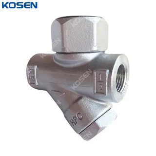
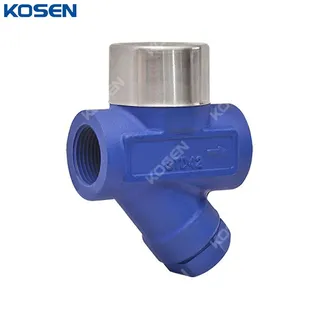
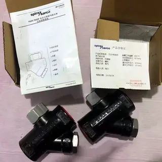
Thermodynamic Steam Traps, A351 CF8, 1/2 IN, CL150, Threaded
Key Specifications / Features
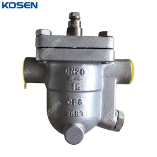
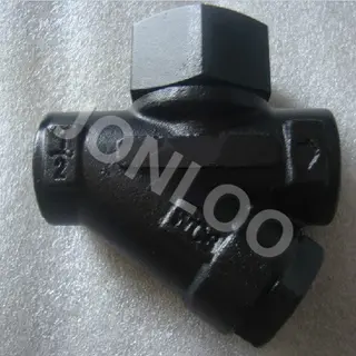
The Thermodynamic Steam Traps designed for superior performance and durability. These traps feature a cast stainless steel body made from ASTM A351 CF8 material, ensuring excellent corrosion resistance and longevity. With a compact 1/2 inch (DN15) size and a pressure rating of 150 LB (PN16), they are ideal for applications requiring high efficiency in smaller systems. The TD16T threaded ends provide easy installation and secure connections. These steam traps are engineered to effectively remove condensate while preventing steam loss.
Detail Information
Product Name: ASTM A351 CF8 Thermodynamic Steam Trap
Body Material: ASTM A351 CF8
Size: 1/2 Inch, DN15
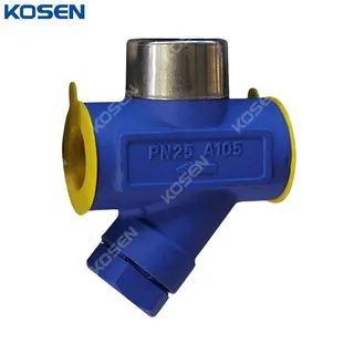
Pressure: Class 150 LB, PN16
End Connection: TD16T Threaded
Medium: Steam Condensate
The Thermodynamic Steam Traps are designed for use in steam pipelines and equipment to prevent steam leakage and eliminate condensate, thereby conserving energy and preventing issues such as water hammer and other faults. By leveraging thermodynamic characteristics, secondary evaporation occurs when condensate water is discharged into a lower pressure zone. The drain valve opens or closes based on the differing viscosity and density of steam.
Technical Specification
» Product Model: TD 16T Thread
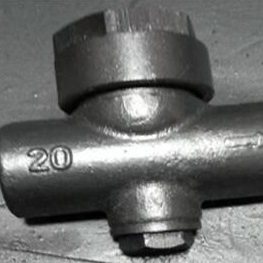
» Normal Size Range: 1/2-1 Inch (DN15-DN25)
» Normal Pressure Rating: PN16, PN25, Class 150 LB
» Material: A743 CA40F, ASTM A351 CF8
» PMA (Maximum Allowable Pressure): 40 Bar g
» TMA (Maximum Allowable Temperature): 300°C
» Maximum Differential Pressure (ΔPMAX): 32 Bar
» Medium: Steam Condensate
Product Features
» The working principle of the thermodynamic steam trap relies on the difference in vapor and liquid density.
» The valve body and bonnet are constructed from forged steel or cast steel.
» The valve clack and valve seat are made from special stainless steel. These components undergo heat treatment and aging treatment, ensuring they remain stable and wear-resistant under high temperature and high pressure conditions, thereby extending the service life of the trap.
» The stainless steel heat preservation cover isolates and reduces heat loss, preventing air locking within the trap.
» The internal fluid channel is designed in strict accordance with the Bernoulli equation, ensuring a rational and efficient structure.
» A built-in filter ensures the trap operates in a clean environment.
» The back pressure rate is as high as 80%.
Structural Diagram
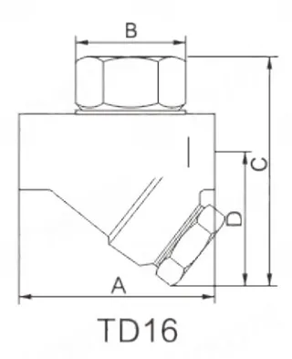
Main Dimensions
|
Size |
A |
B |
C |
D |
Weight |
|
DN15 |
78 |
57 |
96 |
55 |
0.8 |
|
DN20 |
85 |
57 |
104 |
60 |
1.0 |
|
DN25 |
95 |
57 |
113 |
65 |
1.5 |
Send your message to this supplier
FAQs
Similar Products
Related Searches
Products you might also like


Zhejiang Kosen Valve Co., Ltd.
- https://www.kosenvalve.com/
- Business Type: Industry & Trading , Manufacturer
Source: https://www.kosenvalve.com/thermodynamic-steam-traps-a351-cf8-1-2-in-cl150-threaded.html