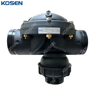
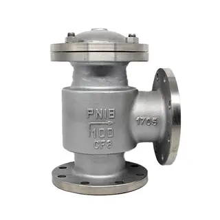
Hydraulic Drive Diaphragm Control Valve, Plastic, DN50-DN100
Key Specifications / Features
Detail Information
Product Name: Hydraulic Drive Diaphragm Control Valve, Filter Backwash Hydraulic Valve
Main Material: Plastic
Max Flow: 80 m3/H
Sizes: 2 Inch, 3 Inch, 4 Inch (DN50-DN100)
Working Pressure: 0.7-10 bar
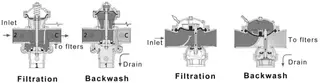
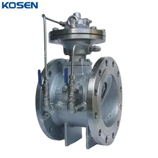
The Filter Backwash Hydraulic Valve is a compact, T-shaped 3-port valve featuring a double-chamber, hydraulically operated, diaphragm-actuated design. It can be paired with a gravel filter or disc filter to form an automatic backwash filtration system, or used in water supply lines to change the flow direction. The valve’s two control chambers allow conversion between angular and straight flow by altering the spring assembly orientation. Its unique cavity design ensures a high water flow capacity, making it suitable for both automated back-flushing filtration and water supply rerouting applications.
Product Features
» Hydraulic-driven diaphragm control valve
» Unique plastic spool assembly design with tight sealing and corrosion resistance
» Short valve stroke stabilizing water flow and preventing mixing of clean and dirty water
» Corrosion-proof, long-lasting material
» Unique cavity design ensuring high water flow
» Easily dismantled drive system for convenient on-line inspection and maintenance
» Dual-chamber valve design with low-voltage drive for effective diaphragm protection
» Option to install changeover joints in the drain of the direct-flow valve (4 to 3, 3 to 2) to meet small-flow requirements
» Dual-chamber design allowing both angular and direct flow, with no installation direction limitations
Structural Diagram
Model & Specification
|
Model |
Size |
Connections |
Max Flow(m3/h) |
Max Pressure(bar) |
Weight(kg) |
|
K63FM |
2 Inch * 2 Inch * 2 Inch |
BSP/NPT/VIC |
30 |
0.7-10 |
2.8 |
|
K90FM |
3 Inch * 3 Inch * 3 Inch |
VIC |
50 |
0.7-10 |
5.5 |
|
K110FM |
4 Inch * 4 Inch * 4 Inch * (3 Inch) |
VIC |
100 |
0.7-10 |
9.9 |
|
K110FMS |
4 Inch * 4 Inch * 3 Inch * (4 Inch) |
VIC |
80 |
0.7-10 |
5.5 |
Send your message to this supplier
FAQs
Similar Products
Related Searches
Products you might also like
Zhejiang Kosen Valve Co., Ltd.
- https://www.kosenvalve.com/
- Business Type: Industry & Trading , Manufacturer
Source: https://www.kosenvalve.com/hydraulic-drive-diaphragm-control-valve-plastic-dn50-dn100.html