How to Choose the Right Control Valves for Your Process
In industrial production, control valves are indispensable key devices in automated control systems. They are responsible for receiving signals from the control system and adjusting the flow, pressure, temperature, and other parameters of the medium in pipelines by changing the valve opening, thereby ensuring stable operation of the production process. However, facing the wide variety of control valve products on the market, how to select a control valve that meets both process requirements and cost-effectiveness is a practical problem many engineers face. This article systematically explains control valve selection methods from multiple dimensions, including structural form, flow characteristics, sizing, material selection, and actuators, helping readers master a scientific approach to valve selection.
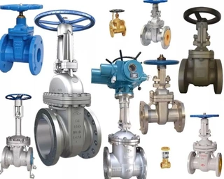
Selection of Structural Form
Control valves come in a variety of structural forms. In actual engineering applications, the most common types are single-seat control valves, double-seat control valves, sleeve-guided control valves, and butterfly valves. Choosing the appropriate structural form requires comprehensive consideration of process conditions, medium characteristics, and system requirements.
- Single-Seat Control Valve: The single-seat control valve is the most basic and widely used type. Its structural feature is having only one plug and one seat, providing good sealing performance and low leakage. In cases with small flow, small pressure drop, and strict leakage requirements, selecting a single-seat control valve can meet production needs, and it is relatively inexpensive with high cost-performance. For example, in precision flow control processes in fine chemical or pharmaceutical industries, single-seat control valves are often the preferred choice.
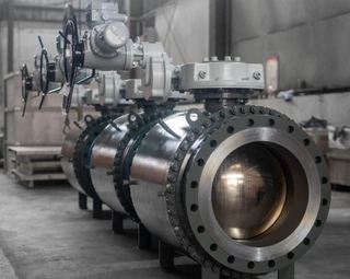
- Double-Seat Control Valve: When a process system needs to handle large flow and high-pressure drop conditions, double-seat control valves show their unique advantages. Double-seat valves have two plugs and two seats. The fluid forces on the upper and lower plugs act in opposite directions and can cancel out most of the unbalanced force, so the actuator requires less thrust and can handle larger pressure drops. Although their sealing performance is not as good as single-seat valves, and leakage is relatively higher, in situations where leakage requirements are not strict, double-seat control valves are a priority choice. Typical applications include large water supply systems and main steam pipelines.
- Sleeve-Guided Control Valve: Sleeve-guided valves use a sleeve-guided structure, with the plug moving up and down within the sleeve. This design provides good stability, can withstand larger pressure drops, and has strong vibration resistance. This structure is particularly suitable for high-pressure-drop media or conditions with significant vibration. For example, at compressor outlets or high-pressure-reducing stations, sleeve-guided valves can effectively overcome fluid impact and vibration, ensuring long-term stable operation.
- Butterfly Valve: Butterfly valves have a simple structure, are compact and lightweight, and are low in cost. They are widely used for regulating pressure and flow in low-pressure gas pipelines. They are suitable for regulating low-pressure gases such as air or town gas, with advantages particularly obvious in large-diameter pipelines. Butterfly valves are widely used in urban gas distribution and HVAC systems for flow regulation.
Selection of Flow Characteristics
The flow characteristic of a control valve describes the relationship between valve opening and flow rate, which is a key parameter to consider during selection. Common flow characteristics include equal percentage, linear, parabolic, and quick-opening. Different flow characteristics suit different control objects, and incorrect selection can directly affect the quality and stability of the automatic control system.
- Equal Percentage Characteristic: Also known as logarithmic characteristic, equal percentage means that for each equal increment of valve opening, the flow increases by the same percentage of the current flow. The advantage is that flow changes smoothly at small openings and sensitively at large openings, maintaining consistent control accuracy across the entire stroke. Because this characteristic matches the heat transfer characteristics of most heat exchangers, it is the most commonly used in engineering applications, especially for temperature, pressure, and flow control systems.
- Linear Characteristic: Linear characteristic means the relative flow is linearly proportional to the relative valve opening, so the flow change is the same for the same opening change. At small openings, the flow change rate is relatively high, which may cause overshoot and oscillation; at large openings, the flow change rate is relatively small, making control less sensitive. Linear characteristics are suitable for situations with small pressure variations, small adjustment ranges, and small opening changes, such as liquid level control systems. In these specific applications, linear characteristics can provide good control.
- Parabolic Characteristic: Parabolic characteristic means the flow is proportional to the square root of the valve opening, offering control performance between linear and equal percentage characteristics. It improves the poor control performance of linear characteristics at small openings and is suitable for applications requiring moderate control. V-ball valves often use parabolic characteristics and perform well in precise control of particulate or fibrous media.
- Quick-Opening Characteristic: Valves with quick-opening characteristics achieve a large flow at small openings, and as the opening increases, the flow quickly reaches the maximum. This characteristic is mainly used in situations requiring rapid opening and closing, such as emergency shutdown systems or two-position control systems. Disc-type valves typically adopt quick-opening characteristics, allowing full open or full close in a short time to meet safety requirements.
Valve Sizing
The valve size directly affects its control performance and economy. If the valve is oversized, it frequently operates at small openings, which can erode the plug and shorten service life. If undersized, it cannot meet the maximum flow requirements. A commonly used method is the flow coefficient (C) method, also known as the capacity method.
1. Detailed Calculation Steps
First, determine the valve structural form and flow characteristic according to process conditions and control requirements. Then, identify the calculation method and formula for the flow coefficient C. For liquid media, viscosity correction should be considered; when viscosity is too high, Reynolds number decreases, changing the flow regime, requiring a viscosity correction factor. For gas media, compressibility must be considered. For steam media, it is necessary to distinguish between saturated and superheated steam, using different formulas.
Next, substitute the process parameters into the formula to calculate the maximum flow flow coefficient C_max. Then, in the standard valve rating table, select the Cv closest to 1.2 × C_max; the corresponding valve diameter is the preliminary valve size.
2. Opening Verification and Adjustment
After selecting the size, opening verification must be conducted. At maximum flow, the valve opening generally should not exceed 85% to reserve control margin; at minimum flow, it should not be less than 20% to avoid plug erosion at small openings. If verification results are unsatisfactory, select another rated Cv and recalculate until satisfactory results are obtained.
For determining maximum flow, typically 1.15–1.5 times the steady-state maximum flow is used as the calculation basis, depending on the designer's experience and assessment of process fluctuations. A reasonable margin meets production fluctuation needs while avoiding excessive valve oversizing.
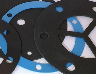
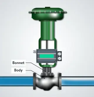
Principles of Material Selection
Material selection involves pressure-bearing parts (body, bonnet) and throttling parts (stem, plug, seat), and must consider medium temperature, pressure, and corrosiveness.
1. Body and Bonnet Materials
The body and bonnet are equivalent to pressure vessels and must withstand the medium’s temperature, pressure, and corrosion. Nominal pressure selection must reference process temperature, as nominal pressure is based on material strength at a reference temperature. When temperature rises, material strength decreases, and allowable working pressure must be correspondingly reduced.
For example, for a carbon steel valve with PN1.6 MPa:
- At 200°C, maximum pressure is 1.6 MPa
- At 250°C, maximum pressure is 1.5 MPa
- At 400°C, maximum pressure is only 0.7 MPa
High-temperature conditions require high-temperature materials or valves with higher pressure ratings.
2. Internal Component Materials
Internal components (stem, plug, seat) perform throttling functions and must resist corrosion and erosion. Common materials include 304 stainless steel, 316 stainless steel, 17-4PH precipitation-hardening stainless steel, and tungsten-chrome-cobalt alloy hard metals. For highly corrosive media, special alloys like Hastelloy or titanium may be required.
The general principle is: ensure safety and reliability first, select materials resistant to high or low temperature, high pressure, cavitation, and corrosion according to process characteristics; while also considering performance, service life, and cost-effectiveness.
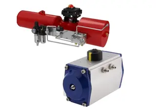
Actuator Types
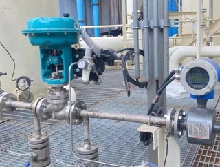
Control valve actuators include pneumatic, electric, and electro-hydraulic types. Pneumatic actuators are divided into diaphragm and cylinder types, offering simple structure, reliable operation, and good explosion-proof performance, widely used in flammable and explosive petrochemical environments. Electric actuators provide high precision and are suitable for applications requiring accurate control. Electro-hydraulic actuators offer large thrust for high-pressure-drop, large-diameter valves.
Actuators can also be classified by action when the signal or drive source disappears: direct-acting, reverse-acting, non-directional, and holding type. Direct-acting valves rise when the signal or air supply disappears; reverse-acting valves descend. Selection should consider fail-safe requirements.
Flow Direction and Fail-Safe
For valves with specific flow direction requirements, select flow-to-open or flow-to-close types accordingly. Single-seat valves are generally flow-to-open; high-pressure valves with DN ≤ 20 are flow-to-close; for DN > 20, stability determines choice. Angle valves with high-viscosity or solid-laden media are flow-to-close to ensure self-cleaning; single-seal sleeve valves with self-cleaning requirements are also flow-to-close.
Fail-safe position selection is critical. In case of power or air failure, valve fault, or process abnormality, emergency shutdown may be required, and the valve must be in a safe position, either fail-open or fail-closed. This must comply with process safety requirements to prevent harm to personnel or equipment.
Summary of Selection Process
Determine process medium type (liquid, steam, or gas) and physical/chemical properties (viscosity, density, corrosiveness, toxicity, etc.).
- Determine valve structural form based on flow, pressure drop, and leakage requirements.
- Select appropriate flow characteristic according to control target.
- Calculate flow capacity at maximum flow to preliminarily determine valve size and verify stroke.
- Select body and internal component materials according to temperature, pressure, and corrosiveness.
- Select actuator type and fail-safe position based on power source and control requirements.
- Consider special requirements, such as noise reduction, clog resistance, and corrosion resistance, to finalize selection.
If multiple valves meet process requirements, consider service life, maintenance convenience, and cost to choose the most cost-effective option.
Control valve selection is a systematic engineering process requiring coordination among process, instrumentation, and equipment disciplines. Only by fully understanding process requirements, mastering valve characteristics, and following scientific selection methods can one choose a control valve that is safe, reliable, and economically reasonable, ensuring stable operation of the automated control system.
Send your message to this supplier
Related Articles from the Supplier

Related Articles from China Manufacturers

How to Choose the Right Control Valve
- Jan 12, 2026
How to Choose the Right Safe Lock
- Jul 11, 2024

How to Choose the Right Lock for Your Cabinet Doors
- Jul 27, 2024


How to choose the right diaper for your baby
- Feb 15, 2019

Related Products Mentioned in the Article
Supplier Website
Source: https://www.valvepackingsealkits.com/news/how-to-choose-the-right-control-valves-for-your-process.html