Leakage Failure Analysis of an Ultra-High-Pressure Ethylene Plant Pipeline
Abstract: Leakage in ultra-high-pressure steam pipelines is a common issue in ethylene plants. This study investigates the causes of leakage in an ultra-high-pressure pipeline at an ethylene plant through macroscopic examination, material characterization, metallographic analysis, hardness testing, mechanical property testing, and chemical composition analysis. The results indicate that the primary cause of cracking and leakage in the pipeline was the initiation and propagation of scratches on the inner wall under high circumferential stress during pressure testing.
Introduction
In September 2023, abnormal noise was detected on the north side of a pipe rack during pressure testing of an ultra-high-pressure pipeline in an ethylene plant, at a test pressure below 42 MPa. Subsequently, localized water spraying was observed from the base material of a DN25 drain line connected to the ultra-high-pressure pipeline on the north side of the pipe rack. On-site inspection confirmed that the leak occurred in the pipeline section between the pipe rack and a furnace, beneath a horizontal pipeline, with the ultra-high-pressure pipe measuring Φ33.4 × 9.09 mm and manufactured from P22 steel.
1. Inspection and Testing
1.1 Macroscopic Inspection
The submitted ultra-high-pressure pipeline displayed an axial crack groove approximately 680 mm long on its outer wall, along with a near-through-wall crack on the pipe’s end face. Analysis of an axial cross-section revealed two primary cracks and a scratch aligned in the same direction, with Crack 1′ being non-penetrating and Crack 2′ fully penetrating the pipe wall. Upon opening Crack 2′, the fracture surface was relatively flat within an approximately 0.5 mm zone near the inner wall, whereas the surrounding areas displayed typical ductile tearing characteristics, as illustrated in Figures 1 and 2.
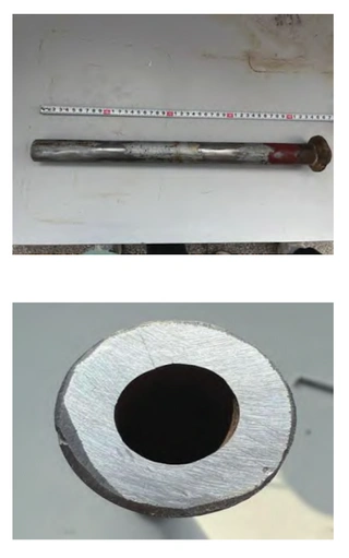
Figure 1 Morphology of the outer wall and end face of the ultra-high-pressure pipeline
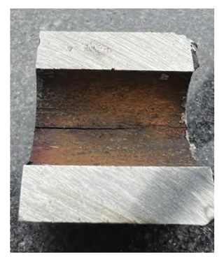
Figure 2 Morphology of the inner wall
1.2 Outer Diameter and Wall Thickness Measurements
The ultra-high-pressure pipeline had a nominal dimension of 33.4 × 9.09 mm, and wall thickness measurements were taken at four circumferential positions. The minimum measured wall thickness was 7.88 mm, reflecting a reduction of 1.21 mm, or roughly 13%. The pipe’s outer diameter, measured at locations away from the cracks, conformed to the allowable tolerances for wall thickness and outer diameter as specified in the Technical Specifications for Ultra-High-Pressure Steam Alloy Steel Pipes of a certain ethylene project. The measurement locations and corresponding results are presented in Table 1.
Table 1 Outer diameter measurement results at locations far from the cracks
|
Measurement location |
Outer diameter (mm) |
|
Far from Crack 1 |
33.64 / 33.80 / 33.70 |
|
Far from Crack 2 |
33.61 / 33.74 / 33.80 |
1.3 Metallographic Examination
Metallographic examinations were carried out on both the end face and the longitudinal section of the ultra-high-pressure pipeline. The pipeline material was identified as P22 steel. The microstructure was composed of ferrite and pearlite, with a grain size corresponding to ASTM grain size number 8. Two cracks were observed on the end face, extending outward from the inner wall, each with a depth of approximately 0.3 mm. These cracks are located at the scratch position indicated in Figure 2. At these locations, the metallographic structure shows distinct flow lines aligned with the crack propagation direction, suggesting that plastic deformation occurred during processing. The non-metallic inclusion ratings were determined to be A1 and B1.5. Both the grain size and the inclusion ratings meet the requirements specified in the Technical Specifications for Ultra-High-Pressure Steam Alloy Steel Pipes for a Certain Ethylene Project. The metallographic results are shown in Figures 4–7.
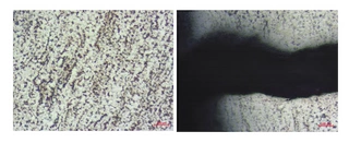
Figure 4 Metallographic structure of the end face
Figure 5 Metallographic structure of the inner wall at the main crack
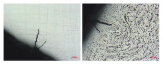
Figure 6 Metallographic structure of the uncorroded inner wall of the end face and its vicinity
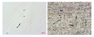
Figure 7 Metallographic structure of non-metallic inclusions and their vicinity
Table 2 Mechanical Property Test Results
|
Property |
Tensile strength (MPa) |
Yield strength (MPa) |
Elongation (%) |
Impact energy (J) |
|
Test values |
505 |
337 |
22.5 |
67.5 / 66.0 / 68.0 |
|
Technical specification |
≥415 |
≥205 |
≥20 |
≥40 |
Table 3 Chemical Composition Analysis Results (wt%)
|
Element |
C |
Mn |
Si |
P |
S |
Cr |
Mo |
|
Test value |
0.13 |
0.49 |
0.27 |
0.015 |
0.0069 |
1.93 |
0.92 |
|
Technical specification |
0.05–0.15 |
0.30–0.60 |
≤0.50 |
≤0.015 |
≤0.010 |
1.90–2.60 |
0.87–1.13 |
1.4 Hardness Testing
Hardness tests were conducted on the end face of the ultra-high-pressure pipeline. The measured hardness values are shown in Figure 8. According to the Technical Specifications for Ultra-High-Pressure Steam Alloy Steel Pipes for a Certain Ethylene Project, the allowable hardness range is 147–190 HB. All measured values fall within the specified range and therefore meet the technical requirements. Measured hardness values (HB): 151, 157, 151, and 153.
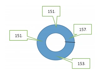
Figure 8 Hardness values measured on the end face of the ultra-high-pressure pipeline
1.5 Mechanical Property Testing
Mechanical property tests were conducted on representative samples. The test results, provided by a certified testing organization, meet the requirements specified in the Technical Specifications for Ultra-High-Pressure Steam Alloy Steel Pipes for a Certain Ethylene Project, as summarized in Table 2.
1.6 Chemical Composition Analysis
The chemical composition of the sampled material was analyzed, and the results comply with the requirements specified in the Technical Specifications for Ultra-High-Pressure Steam Alloy Steel Pipes for a Certain Ethylene Project (Table 3).
2. Failure Analysis
The submitted ultra-high-pressure pipeline meets the requirements specified in the Technical Specifications for Ultra-High-Pressure Steam Alloy Steel Pipes for a Certain Ethylene Project with respect to chemical composition, hardness, mechanical properties, dimensional accuracy, metallographic structure, non-metallic inclusions, and grain size.
Macroscopic examination revealed a non-through crack extending from the inner wall toward the outer wall, indicating that the crack initiated at the inner surface of the pipe. In addition, a through-wall crack was identified, which directly caused leakage during the pressure test. A longitudinal scratch was observed on the inner wall in the vicinity of both major cracks, corresponding to a small crack identified during end-face metallographic examination. The observations suggest that the scratch acted as a site of stress concentration. Under this stress condition, the inner-wall scratch initiated a crack, which then propagated through the pipe wall, ultimately resulting in leakage.
3. Conclusions
During the hydrostatic pressure test, high circumferential stress caused a pre-existing scratch on the inner wall of the ultra-high-pressure pipeline to initiate cracks, which subsequently propagated and led to leakage in the ethylene plant.
Send your message to this supplier
Related Articles from the Supplier

Related Articles from China Manufacturers
Failures Caused by Leakages of Valves
- Apr 28, 2022
Leakage Cases Happen to Seal Gaskets of Flanges
- Jul 28, 2014

Packing Leakage of Control Valves
- Apr 28, 2022
Seal Leakage of Ball Valves Stem
- Jul 30, 2022
Related Products Mentioned in the Article
Supplier Website
Source: https://www.steel-pipes.com/news/leakage-failure-analysis-of-an-ultra-high-pressure-ethylene-plant-pipeline.html