Welding 600 MPa High-Strength Steel for Pressure Pipes in Pumped Storage Stations
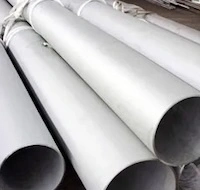
Abstract: Pressure steel penstocks are the primary load-bearing components of water conveyance systems in pumped storage power stations and play a critical role in ensuring operational safety, functional performance, and the timely progress of construction projects. Due to their high strength and excellent toughness, 600 MPa-class and higher-strength steels are widely used in the fabrication of these penstocks. Using the branch steel penstock fabrication project at the Huizhou Zhongdong Pumped Storage Power Station as a case study, this research investigates welding consumables, methods, and parameters for high-strength steels. Based on the experimental results, an optimized welding scheme is proposed, offering a valuable reference for promoting the application and technological advancement of high-strength steels in pressure steel penstock fabrication for pumped storage power stations. The Huizhou Zhongdong Pumped Storage Power Station is located in Zhongdong Village, Gaotan Town, Huidong County, Huizhou City, Guangdong Province, China. The station has a planned installed capacity of 1,200 MW and consists of three reversible pump-turbine generator units, each with a capacity of 400 MW. The main facilities include an upper reservoir, a lower reservoir, a water conveyance system, an underground powerhouse cavern complex, a surface switchyard, and permanent internal access roads. Within the water conveyance system, the branch steel penstocks have diameters ranging from DN3000 to DN2270 mm and steel plate thicknesses of 44–95 mm, and are fabricated from Q490S, a 600 MPa-class high-strength steel. Based on the fabrication project of these branch pressure steel penstocks, this paper investigates the key welding parameters for 600 MPa-class high-strength steel and identifies the optimal welding methods, consumables, and parameters.
1. Welding Experiments
(1) The tensile, bending, and impact properties of the Q490S steel plates were tested in strict accordance with Clause 6.4 of GB/T 31946-2015, Steel Plates for Pressure Steel Penstocks of Hydropower Stations.
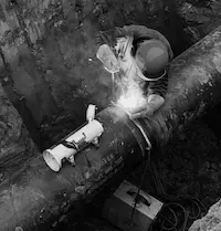
(2) The steel plates were welded using two methods: pure gas-shielded welding and a hybrid approach combining gas-shielded welding with submerged arc welding. Welding consumables were obtained from manufacturers and brands including Jinertai, Mudan, and Lincoln. Details of the experimental comparisons are provided in Table 1.
The primary difference between Test Plate 1 and Test Plate 2 was the choice of welding consumables, whereas the variation between Test Plate 3 and the other two plates was mainly due to differences in welding methods and parameters. After completing all three sets of experiments, the test specimens were thoroughly evaluated for their tensile, impact, and bending properties.
(3) Welding of the test plates was conducted under strict conditions:
- Before welding, electrodes and fluxes were baked and kept at the temperatures specified by the manufacturers. During welding, unused electrodes were stored in an electrically heated holding oven and retrieved only as needed, with the oven lid kept closed at all times. Electrodes were not allowed to remain in the oven for more than four hours; if this time was exceeded, they had to be re-baked, with a maximum of two re-baking cycles permitted.
- Before welding, all mill scale, rust, oil, and other contaminants were thoroughly removed from the weld zone and groove flanks within 15–20 mm. After each weld pass, the surface was promptly cleaned, and the next pass was started only after a self-inspection confirmed no defects.
- For automatic submerged arc welding, run-on (arc-starting) and run-off (arc-extinguishing) plates were attached at both ends of the weld seam. The material, groove configuration, and dimensions of these plates matched the workpiece, with typical dimensions of at least 50 mm × 100 mm.
- In multi-pass welding, inter-layer joints (tie-ins) were staggered by at least 30 mm, and each weld seam was completed continuously in a single pass. If welding was interrupted, the weld surface was thoroughly cleaned before resuming, and welding continued according to the original procedure only after confirming that no cracks or other defects were present.
2. Experimental Results
2.1 Weld Quality Inspection
2.1.1 Visual Inspection of Welds
The weld seams on all three test plates were visually inspected in strict accordance with GB/T 50766, “Code for Fabrication, Installation, and Acceptance of Pressure Steel Pipes for Hydropower and Water Conservancy Projects,” with a thorough examination of the entire weld surface. All three test plates’ weld seams displayed a uniform, smooth profile, featuring a natural, seamless transition to the base metal without any noticeable height differences or misalignment. No crack-type defects, including linear or crater cracks, were found on the weld surfaces or within the heat-affected zones, and no undercut exceeding 0.5 mm in depth or 10 mm in length was detected at the interface between the weld edges and the base metal. Furthermore, the weld surfaces were free of visible pores—circular, elliptical, or elongated—as well as other surface defects, including slag inclusions, incomplete penetration, and weld overlap. Cross-sectional analysis of the weld seams revealed a full, convex profile, with weld reinforcement consistently maintained between 2 and 4 mm, and a uniform weld width fully covering the entire groove area. These results indicate excellent stability of the welding process and strict compliance with standard operational procedures.
2.1.2 Non-Destructive Testing of Internal Weld Quality
To assess the internal quality of the weld seams on all three test plates, ultrasonic testing (UT) was performed in strict accordance with GB/T 11345, "Manual Ultrasonic Testing of Steel Welds and Classification of Testing Results," and the project-specific inspection plan. The purpose was to thoroughly detect potential internal defects, including slag inclusions, incomplete penetration, lack of fusion, or internal cracks. Before testing, the inspection equipment was carefully calibrated to ensure high-precision performance. The weld inspection surfaces were pre-treated to remove spatter, mill scale, and oil, with surface roughness controlled to a maximum Ra of 6.3 µm to ensure effective acoustic coupling and prevent interference with ultrasonic signals. The inspection used a combination of zigzag and oblique parallel scanning, ensuring complete coverage of the weld seam cross-sections. Ultrasonic couplant was applied evenly, the scanning speed was limited to 150 mm/s, and adjacent passes overlapped by at least 15%; any suspicious signals were re-examined multiple times for accurate localization. Systematic inspection and data analysis detected no defect signals exceeding the specified standards. Specifically, no point-like slag inclusions exceeded 3 mm, no linear slag inclusions surpassed one-third of the weld thickness, and there were no instances of incomplete penetration or lack of fusion along the fusion lines or groove roots. Additionally, no internal cracks or other critical defects were detected. All inspection results comply with Class I weld standards defined in GB/T 11345, demonstrating that the internal weld structure is sound, dense, and exhibits reliable mechanical properties and operational safety.
2.2 Performance Testing
2.2.1 Test Items
Mechanical performance tests were carried out on the base metal and the three welded test plates in strict accordance with the relevant national standards. The tests were conducted following GB/T 228.1 (Metallic Materials—Tensile Testing, Part 1: Method at Room Temperature), GB/T 232 (Metallic Materials—Bend Test), and GB/T 229 (Metallic Materials—Charpy Pendulum Impact Test). A systematic experimental design was implemented to thoroughly evaluate the fundamental mechanical properties of the base metal and the integrity of the welded joints.
(1) Tensile Testing
Representative specimens were extracted from the base metal, weld zones, and heat-affected zones of the three test plates. The specimens were machined to standard dimensions according to the relevant standards and tested using a microcomputer-controlled electronic universal testing machine.
The primary objective was to evaluate the mechanical behavior of both the base material and the welded joints under axial tensile loading. By analyzing the stress–strain relationships, the study aimed to determine whether the materials have sufficient load-bearing capacity and to assess the effect of the welding process on material strength, ensuring that the welded joints do not compromise overall structural integrity.
(2) Bending Testing
Using the standard three-point bending method, specimens from both the base metal and the test plates were carefully mounted on the support fixture of a bending test machine. Load was applied gradually, following the specified mandrel diameter and loading rate, until the specimens reached the predetermined bending angle. The test was designed to evaluate the plastic deformation capacity and overall integrity of both the base material and the weld seam, with particular focus on identifying any hidden brittle defects or incomplete fusion within the welded joints. After testing, a visual inspection of the specimen surfaces was conducted to assess their resistance to cracking under bending loads.
(3) Impact Testing
Impact testing was conducted to assess the materials’ toughness under dynamic loading, using Charpy V-notch specimens tested at –40 °C with a pendulum impact testing machine. The primary objective was to evaluate the impact resistance of both the base metal and welded joints under severe, low-temperature conditions. By measuring the energy absorbed during impact, the test assessed the resistance of the base metal and welded joints to sudden fracture, helping to reduce the risk of brittle failure during service caused by low-temperature embrittlement.
Table 1. Experimental Specimens for Each Group
|
Test Plate |
Steel Plate Thickness (mm) |
Steel Plate Material |
Welding Method |
Groove Form |
Welding Consumables |
Manufacturer/Brand |
Welding Current (A) |
Welding Voltage (V) |
Welding Speed (mm/min) |
|
Test Plate 1 |
66 |
Q490SE |
Gas-shielded welding (Root pass) |
Symmetrical double-sided 30° groove, 2 mm root face |
NilK+8500 |
Lincoln |
180–220 |
20–25 |
120–180 |
|
|
|
|
Submerged arc welding (Fill pass) |
|
|
|
500–600 |
26–30 |
350–400 |
|
Test Plate 2 |
66 |
Q490SE |
Gas-shielded welding (Root pass) |
Symmetrical double-sided 30° groove, 2 mm root face |
JET-81K2 Ø1.2 |
Jinertai |
180–220 |
20–25 |
120–180 |
|
|
|
|
Submerged arc welding (Fill pass) |
|
HO8CG Ø4.0 + ST102G |
Mudan |
500–600 |
26–30 |
350–400 |
|
Test Plate 3 |
66 |
Q490SE |
Gas-shielded welding |
Symmetrical double-sided 30° groove, 2 mm root face |
JET-81K2 Ø1.2 |
Jinertai |
170–260 |
23–30 |
130–300 |
Using the standard three-point bending method, the base metal and test plate specimens were firmly secured on the support fixture of a bending test machine. Load was applied gradually, according to the specified mandrel diameter and loading rate, until the specimens reached the predetermined bending angle. This test primarily evaluates the plastic deformation capacity and overall integrity of both the base material and the weld seam, with a focus on detecting any hidden brittle defects or incomplete fusion within the welded joint. After testing, visual inspection of the specimen surfaces assesses the material’s resistance to cracking under bending stresses. Impact testing evaluated the materials’ toughness under dynamic loading, using Charpy V-notch specimens tested at −40 °C on a pendulum impact machine to apply instantaneous impact forces. The main objective was to assess the impact resistance of both the base metal and welded joints under extreme low-temperature conditions, confirming that the materials have sufficient toughness to effectively absorb impact energy. By measuring the absorbed impact energy, the test evaluates the fracture resistance of both the base metal and welded joints under sudden loading, reducing the risk of brittle failure in structural components during service caused by low-temperature embrittlement.
2.2.2 Comparative Analysis
Based on the experimental results described above, the tensile strength and bending performance of the three test plates were largely consistent; however, the impact energy values of Test Plates 2 and 3 were significantly lower than those of Test Plate 1.
(1) Tensile Strength
Overall, the tensile test results met the required standards and showed excellent consistency. The measured tensile strengths of the three test plates were highly uniform: Test Plate 1 reached 630 MPa, Test Plate 2 reached 640 MPa, and Test Plate 3 reached 628 MPa. The variation among the samples was only 12 MPa, with all values falling within the range of 620–650 MPa. This indicates that the welding process exhibits strong stability in terms of strength control, as the tensile strength did not fluctuate significantly due to differences in welding heat input. Compared with the base metal tensile strength of 708 MPa, the tensile strengths of the test plates were slightly lower but still met typical engineering requirements. This minor reduction is likely attributable to microstructural changes in the heat-affected zone, such as slight grain coarsening, without compromising the overall load-bearing capacity of the welded joints.
(2) Bending Performance
All specimens successfully passed the bending test, demonstrating adequate plastic deformation capacity. The bending results for the base metal and all three test plates showed no cracks, meeting the Level I acceptance criteria of GB/T 232, which specify that no visible cracks or fractures shall appear on the specimen surface after bending. This confirms that the base metal possesses excellent plastic deformation capacity and strong resistance to brittle fracture under bending loads. Additionally, the welded joints—including the weld center, fusion line, and heat-affected zone—were free of hidden brittle defects, such as lack of fusion or microcracks. The welding process did not significantly degrade the material’s plasticity, and the joints are capable of withstanding bending deformation, meeting the structural requirements for both installation and in-service conditions.
(3) Impact Energy
Significant differences were observed in impact performance, especially at the weld centers, with impact energy serving as a key indicator of material toughness and resistance to fracture under sudden loading. In this study, significant differences were observed between the weld centers and heat-affected zones, as well as among the weld centers of the three test plates. First, regarding the impact energy of the heat-affected zones, Test Plates 1 and 2 performed excellently, while Test Plate 3 exhibited significantly lower values. The average impact energies of the heat-affected zones were 233 J and 232 J for Test Plates 1 and 2, respectively, demonstrating high toughness and confirming that these zones did not develop embrittling microstructures, such as martensite or coarse ferrite, during welding. In contrast, the heat-affected zone of Test Plate 3 exhibited an average impact energy of only 59 J—about 25.3% of Test Plate 1’s value—indicating a substantial reduction in toughness. Second, impact energy at the weld center: Test Plates 1 and 3 displayed normal performance, whereas Test Plate 2 showed an unusually low value. The average impact energies at the weld centers of Test Plates 1 and 3 were 179 J and 176 J, respectively, indicating uniform fine-grained ferrite and pearlite microstructures, with no significant solidification defects such as segregation, porosity, or slag inclusions. Conversely, the weld center of Test Plate 2 exhibited an average impact energy of only 35.3 J—approximately 19.7% of Test Plate 1’s value—indicating an abnormally low toughness.
3. Conclusion
Based on the welding experiments conducted for the fabrication of branch pressure steel penstocks at the Huizhou Zhongdong Pumped Storage Power Station, a systematic investigation was carried out into the welding process characteristics of Q490S, a 600 MPa-class high-strength steel. The key findings are as follows:
- Influence of Welding Consumables and Methods: Different combinations of welding consumables and techniques significantly affect weld quality. Some welding schemes exhibited superior process stability and joint performance, underscoring the importance of selecting appropriate consumables and procedures.
- Weld Quality Assurance: Inspection results show that the established welding processes yield uniform welds with smooth transitions, free of internal defects beyond allowable limits. These results fully meet the Class I weld quality requirements.
- Mechanical Properties: Mechanical testing indicates that correct welding parameters ensure the joints meet the required tensile strength and bending performance while maintaining sufficient plasticity reserves. However, the impact toughness at the weld center and in the heat-affected zone (HAZ) is highly sensitive to the selection of welding consumables and variations in welding methods. Certain welding schemes resulted in reduced toughness, underscoring the importance of careful process optimization.
- Optimal Welding Scheme: employing a specific brand of welding consumables, combined with a hybrid approach—gas-shielded welding for the root pass and submerged arc welding for the fill passes—effectively balances the strength and toughness of high-strength steel welded joints. This constitutes an optimal welding scheme for fabricating 600 MPa-class pressure steel pipes and offers reliable technical guidance for similar engineering projects.
This study provides a solid foundation for the application of 600 MPa-class high-strength steel in welded pressure pipes for pumped storage power stations. Nevertheless, as these facilities operate under increasingly demanding conditions, welding technology for high-strength steels will need further refinement. Future research could focus on welding processes for even higher-strength steel grades, investigating more suitable consumables and advanced heat-input control techniques to satisfy stricter operational requirements. Additionally, integrating intelligent welding technologies could enable automated control of welding parameters, enhancing both weld quality stability and production efficiency.
Send your message to this supplier
Related Articles from the Supplier

Related Articles from China Manufacturers
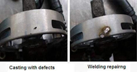
Welding Defects and Repair Welding of Valves
- Mar 08, 2021

Welding Methods of Aluminum Alloys
- Apr 09, 2022

Welding Materials for Aluminium
- Apr 22, 2022

Welding requirement for pressure vessels
- Apr 25, 2017

Welding requirement for gas storage tank
- Jul 27, 2017

Related Products Mentioned in the Article
Supplier Website
Source: https://www.landeepipe.com/welding-600-mpa-high-strength-steel-for-pressure-pipes-in-pumped-storage-stations.html