
Monoflange Valve vs. Manifold Valve: What is the Difference
In industrial pressure measurement systems, the connection method between instruments and process pipelines directly affects measurement accuracy, system safety, and maintenance efficiency. As two widely used integrated connection solutions, Monoflange Valves and Manifold Valves are gradually replacing traditional installations that rely on multiple separately mounted valves. A Monoflange Valve integrates multiple valve functions into a compact flanged body, enabling direct installation while reducing leakage points. A Manifold Valve, through its multi-valve assembly structure, provides flexible and reliable solutions for differential pressure measurement and remote installation applications.
This article systematically introduces Monoflange Valves and Manifold Valves from the perspectives of basic concepts, structural features, working principles, manifold types, installation methods, and selection methods, helping engineers and technicians make informed decisions in practical industrial applications.
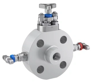
What Is a Monoflange Valve?
A Monoflange Valve is a compact valve assembly used in industrial pressure measurement systems. It integrates functions that traditionally required multiple separate valves into a single compact structure. In industries such as oil and gas, chemical processing, and power generation, pressure transmitters and pressure gauges must be connected to process pipelines, and the Monoflange Valve serves as a key connection component.
A Monoflange Valve is usually mounted directly onto the flange connection of the process pipeline. It commonly integrates functions such as isolation valves and vent valves within the valve body. Compared with conventional installation methods, a Monoflange Valve eliminates the need for additional impulse piping and numerous fittings, thereby simplifying the system structure.
What Is a Manifold Valve?
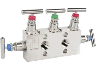
A Manifold Valve is a multi-valve assembly primarily used in differential pressure measurement systems. It consists of several needle valves combined in a specific configuration to perform functions such as isolation, equalization, and venting. Common manifold configurations include 2-valve manifolds, 3-valve manifolds, and 5-valve manifolds.
Manifold Valves are typically connected to pressure transmitters through impulse tubing, allowing the transmitter to be installed away from the process connection point. This design offers significant advantages in environments involving high temperatures, vibration, or limited installation space.
Structural Features and Advantages of Monoflange Valves
The following sections further explain the structural characteristics of Monoflange Valves and the practical advantages these designs provide in industrial applications.
1. Integrated Compact Design
A Monoflange Valve combines flange connection and valve functions into a single integrated assembly. Precision-machined internal flow passages and valve cavities inside the valve body allow media flow and control. This integrated design eliminates external impulse piping, enabling pressure transmitters to be mounted directly onto the process line.
Due to its compact structure, a Monoflange Valve can significantly reduce the overall installation height of instrumentation systems while minimizing the need for tubing and fittings. In applications with limited space, such as offshore platforms or compact skid-mounted equipment, this advantage is particularly important.
2. Double Isolation and Vent Function
Depending on safety requirements, Monoflange Valves can be configured with different numbers of internal valves. The most basic design is a double-valve structure consisting of one isolation valve and one vent valve. The isolation valve shuts off the process media, while the vent valve releases trapped pressure inside the instrument system.
For corrosive media, hazardous fluids, or critical service conditions, a safer option is the double block and bleed configuration with three valves. This design includes two isolation valves connected in series and one vent valve. Even if the first isolation valve fails to provide a complete seal, the second valve continues to serve as a safety barrier to prevent unintended media leakage.
3. Reduced Leakage Points and Installation Space
Every tubing connection represents a potential leakage point. In traditional systems, multiple separate valves and fittings create more opportunities for leakage. By reducing the number of connection points, a Monoflange Valve directly lowers leakage risks.
At the same time, the overall weight of a Monoflange Valve assembly is generally lower than that of conventional multi-valve systems. Reduced weight not only lowers material costs but also decreases the risk of vibration-related damage. Faster installation also reduces labor costs and improves construction efficiency.
Working Principle of Monoflange Valves
After understanding the structural features and advantages of Monoflange Valves, it is important to examine how the internal flow passages and valve arrangements control media flow and perform pressure measurement functions.
1. Internal Flow Passages and Valve Arrangement
Inside the Monoflange Valve body, drilled passages form interconnected flow channels linked to annular valve cavities. Depending on process requirements and service conditions, the valve body may integrate one, two, or three valves.
In a typical double block and bleed Monoflange Valve, the process media first enters the valve body and remains below the first isolation valve. Once the first isolation valve is opened, the media continues toward the second isolation valve. When both valves are opened, the instrument becomes connected to the process pipeline, allowing pressure measurement to take place.
2. Operation of Two-Valve and Three-Valve Designs
A two-valve Monoflange Valve is commonly used in relatively low-pressure or less critical applications. In this design, one valve isolates the process media while the second valve vents trapped pressure from the instrument side. If an upstream shutoff valve is already installed, this configuration can meet basic safety requirements.
A three-valve Monoflange Valve includes two isolation valves in series together with one vent valve. When measurement must be stopped, operators close the two isolation valves sequentially to isolate the instrument from the process media. Any trapped media between the valves and the instrument can then be discharged through the vent valve and drain outlet. Since the isolation valves are arranged at specific angles, the process media can flow smoothly through the valve passages.
3. Function of the Vent System
The vent function provides several important operational benefits. In some process specifications, the process media must not remain in direct contact with the instrument after measurement stops. The vent line allows residual media to be safely discharged.
In addition, the vent system enables calibration and maintenance to be performed without removing the instrument from the pipeline, improving maintenance efficiency and reducing downtime.
The vent function also prevents pressure accumulation inside the instrument system. Before maintenance or instrument replacement, operators can use the vent valve to confirm that the system has been completely depressurized, ensuring operational safety.
Types and Functions of Manifold Valves
In practical industrial applications, Manifold Valves are widely used integrated valve solutions. By combining multiple valves into a single valve block, Manifold Valves provide more comprehensive control functions than Monoflange Valves, especially in differential pressure measurement systems.
1. 2-Valve Manifold
A 2-valve manifold is the simplest manifold configuration and is commonly used for pressure gauges or static pressure transmitters. It includes one isolation valve and one vent valve. The isolation valve blocks process media from entering the instrument, while the vent valve releases pressure on the instrument side.
With this arrangement, technicians can isolate and depressurize the instrument before maintenance or replacement. A 2-valve manifold is suitable for relatively simple systems requiring only pressure monitoring. Enhanced double block and bleed 2-valve manifolds provide additional safety in applications involving residual pressure risks.
2. 3-Valve Manifold
A 3-valve manifold is widely used in differential pressure transmitter systems. It usually consists of two isolation valves and one equalizing valve. The two isolation valves separately control the high-pressure and low-pressure sides, while the equalizing valve balances pressure between the two sides.
Before starting or stopping measurement, operators can use the equalizing valve to balance pressure and prevent sudden differential pressure shocks that could damage the transmitter. By allowing simultaneous control of both pressure lines, the 3-valve manifold simplifies maintenance and operation while improving measurement accuracy.
3. 5-Valve Manifold
A 5-valve manifold is an upgraded version of the 3-valve manifold. It generally includes two isolation valves, one equalizing valve, and two vent or test valves. The two vent valves separately release pressure from the high-pressure and low-pressure sides.
A 5-valve manifold provides greater flexibility during calibration and maintenance, particularly in applications requiring safe venting and accurate testing. It is widely used in chemical plants, refineries, and other high-performance industrial systems.
4. Monoflange Manifold
A Monoflange Manifold is a more compact integrated structure that combines isolation, venting, and sometimes testing functions into a single flanged valve body. This design is especially suitable for offshore platforms, natural gas distribution systems, and compact instrumentation systems.
Thanks to its integrated structure, a Monoflange Manifold reduces the number of fittings, lowers leakage risks, and saves installation space. It offers clear advantages in harsh environments and confined spaces.
Installation Methods and Application Scenarios
Different installation methods directly affect maintainability, vibration resistance, and environmental adaptability. The following sections explain the common installation methods and application scenarios for Monoflange Valves and Manifold Valves.
1. Direct Mounting
Direct mounting involves connecting the manifold or Monoflange Valve directly to the instrument. This method minimizes tubing length and reduces vibration and leakage risks. It is widely used for field-mounted pressure transmitters, particularly where installation space is limited.
A Monoflange Valve can be mounted directly onto vertical or horizontal flange connections while keeping the instrument upright. Since no impulse tubing is required, problems such as condensation, blockage, freezing, or particle accumulation can also be reduced, improving measurement accuracy and system reliability.
2. Remote Mounting
Remote mounting is suitable for applications where direct access to the process line is impractical or where high temperatures make direct installation unsuitable. The manifold connects to the instrument through impulse tubing, allowing remote installation.
In steam boiler systems, drum level measurement and feedwater systems often require transmitters to be mounted in locations that are easier to maintain and protected from high temperatures. In these cases, Manifold Valves offer clear advantages because the impulse tubing allows the transmitter to be installed away from the heat source.
3. Wall-Mounted or Panel-Mounted Installation
Wall-mounted or panel-mounted installations are commonly used in control rooms or instrument cabinets. This arrangement simplifies maintenance and operation while providing better environmental protection. In applications requiring centralized management of multiple measurement points, panel mounting improves operational convenience.
4. Typical Applications
Monoflange Valves and Manifold Valves are widely used in upstream onshore and offshore oil and gas industries, as well as in chemical processing, power generation, and HVAC systems. In steam boiler pressure monitoring systems, both serve as important interface components connecting boiler systems with pressure measurement instruments.
From small mobile equipment to large industrial facilities, valve manifolds provide extensive application value. By centralizing fluid system control, they help improve system performance while reducing energy costs.
How to Choose the Right Solution
Selecting between a Monoflange Valve and a Manifold Valve is critical to ensuring safe, accurate, and reliable operation of pressure measurement systems.
1. Key Considerations
Several factors should be evaluated during selection. The first is temperature and pressure conditions. High-temperature environments may favor the use of a manifold with impulse tubing so that the transmitter can be installed away from the heat source. High-pressure systems require Monoflange Valves or Manifold Valves with suitable pressure ratings.
Installation space and maintenance requirements are also important. In limited spaces, the compact structure of a Monoflange Valve offers clear advantages. Applications requiring frequent calibration and maintenance may benefit more from the advanced isolation and maintenance functions provided by Manifold Valves.
Vibration conditions should also be considered. Longer connection distances generally increase vibration amplitude, which may cause failures in tubing or connection points. By minimizing system size and connection length, Monoflange Valves effectively reduce vibration risks.
2. Comparison Between Monoflange Valves and Manifold Valves
Monoflange Valves are more suitable for applications requiring compact structures, reduced leakage risks, and lower installation costs. By connecting directly to the process line and eliminating external tubing, they simplify the overall system design. In environments with limited installation space, such as steam main pipelines or standardized pressure measurement points, Monoflange Valves are often the preferred solution.
Manifold Valves are more suitable for complex measurement loops, remote installation requirements, and applications involving frequent calibration and maintenance. Their multi-valve structure provides more complete isolation and maintenance capabilities. In applications such as steam drum level measurement and feedwater systems, where transmitters must be installed away from the process connection, Manifold Valves provide irreplaceable advantages.
3. Importance of Communicating with Suppliers
Since many valve options are available on the market, it is important to consult Monoflange Valve and Manifold Valve suppliers during the selection process. Suppliers can recommend suitable pressure ratings, materials, sealing designs, and connection standards according to specific application requirements.
Correct selection affects not only pressure measurement accuracy but also system safety, maintenance convenience, and long-term operational reliability. Therefore, during pressure measurement system design, engineers should carefully evaluate all operating conditions and work closely with professional suppliers to select the most appropriate solution for the application.
Conclusion
In summary, Monoflange Valves and Manifold Valves are essential connection components in modern industrial pressure measurement systems, each offering distinct structural features and application advantages. Monoflange Valves, with their integrated compact design, reduced leakage points, and minimized installation space requirements, are ideal for applications where space is limited and simplified system structures are preferred.
Manifold Valves, through configurations such as 2-valve, 3-valve, and 5-valve manifolds, provide flexible and reliable solutions for differential pressure measurement, remote installation, and complex maintenance requirements. Whether using a Monoflange Valve or a Manifold Valve, the primary objective is to improve system safety, reduce maintenance complexity, and ensure measurement accuracy through integrated design.
In practical engineering applications, designers should evaluate operating temperature, pressure conditions, installation space, vibration levels, and maintenance frequency before selecting a suitable connection solution. Close cooperation with experienced suppliers is also essential to ensure safe, stable, and efficient operation of pressure measurement systems throughout their entire service life.
Send your message to this supplier
Related Articles from the Supplier
An Complete Guide to Monoflange Valve
- Apr 16, 2026
Related Articles from China Manufacturers
Monoflange, Double Block & Bleed Valves
- Nov 25, 2021
Related Products Mentioned in the Article

Zhejiang Kosen Valve Co., Ltd.
- https://www.kosenvalve.com/
- Business Type: Industry & Trading, Manufacturer,
Supplier Website
Source: https://www.kosenvalve.com/media-hub/monoflange-valve-vs-manifold-valve-what-is-the-difference.html