Guide to Troubleshooting of Pneumatic Ball Valves
Pneumatic ball valves are key actuating components in industrial automation control systems and are widely used for fluid pipeline control in industries such as petroleum, chemical processing, power generation, metallurgy, and pharmaceuticals. Powered by compressed air, they offer advantages including simple structure, convenient operation, fast opening and closing, and reliable sealing. However, during actual operation, pneumatic ball valves are inevitably affected by various factors and may develop different types of faults. This article provides a comprehensive overview of practical technical knowledge, from fault cause analysis and diagnostic methods to maintenance practices, helping engineers quickly identify problems and eliminate failures effectively.
Basic Working Principle of Pneumatic Ball Valves
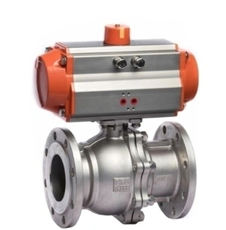
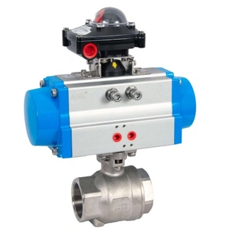
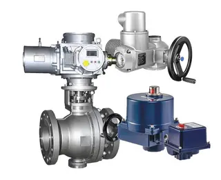
Understanding the working principle of a pneumatic ball valve is the foundation of effective troubleshooting. A pneumatic ball valve mainly consists of two parts: the ball valve body and the pneumatic actuator.
Compressed air generated by an air compressor is delivered to the pneumatic actuator through instrument air piping. After entering the cylinder, the air pushes the piston to move, which drives the valve stem and rotates the ball by 90 degrees, thereby opening or closing the valve. When the air supply is cut off, the spring force inside the actuator returns the valve to its initial position (normally closed or normally open).
The solenoid valve functions as the control element. It receives electrical signals from the control system and regulates the direction of compressed air flow, thereby determining the valve’s switching action.
Common Pneumatic Ball Valve Failures and Cause Analysis
Pneumatic ball valve failures take many forms, primarily including no movement, sticking, leakage, oscillation, and abnormal shutdown. Each is analyzed in detail below.
1. Pneumatic Ball Valve Fails to Operate
A non-responsive valve is the most common fault, and diagnosis should follow the principle of progressing from simple to complex.
First, confirm whether the air supply pressure is normal. Check whether the air compressor is operating, whether the air tank pressure has reached the rated value (typically not lower than 0.4 MPa), and whether the air filter regulator is clogged or set too low. Insufficient air pressure prevents the valve from obtaining enough driving force.
If the air supply is normal, inspect the solenoid valve. Verify whether it is energized, whether the coil is burned out, and whether the spool is stuck. Loss of power in the control circuit prevents the solenoid valve from receiving command signals, leaving the valve closed. Also check whether the inlet and outlet ports are blocked and whether the directional switching operates properly.
When both the air supply and solenoid valve are functioning normally, examine the output of the positioner or electro-pneumatic converter amplifier. If no output is detected, the constant throttle orifice may be blocked, or excessive moisture in the compressed air may accumulate at the amplifier ball valve, forming ice or debris blockage. A fine steel wire can be used to clear the orifice, and air purification should be enhanced.
If all the above checks are normal and a control signal is present but the valve still does not move, the issue likely lies in the actuator or valve body. Possible causes include a bent valve stem, a jammed valve core, damaged internal actuator components, or a disconnected actuator-to-valve linkage. In such cases, the valve must be dismantled for further inspection.
2. Slow Operation or Sticking
Slow valve movement is characterized by a sluggish reciprocating stroke of the valve stem and significantly extended opening and closing times. Major causes include:
Coking or blockage by high-viscosity media inside the valve body
Over-tightened packing that increases friction
Aging PTFE packing that has lost elasticity
Bent or scratched valve stem
Damaged O-ring seals in the cylinder causing air leakage
Reduced spring thrust
Blocked speed controller
Insensitive lock valve at the cylinder outlet
Sticking faults are particularly common in newly commissioned systems or shortly after major overhauls. Welding slag, rust, sand, and other pipeline debris can clog throttling ports and guide sections, restricting medium flow. Excessively tightened packing during maintenance can also increase friction, causing the valve to remain inactive under small signals but overreact under large signals.
3. Abnormal Shutdown or Failure to Open
The causes of abnormal valve shutdown are relatively complex and may include:
Power loss in the control circuit causing the solenoid valve to reset
Air compressor shutdown interrupting compressed air supply
Leakage in instrument air pipelines or insufficient air supply
Failed O-ring seals in the directional valve leading to air loss
Mechanical sticking within the valve itself
During autumn and winter, inadequate insulation or heat tracing may allow the fluid medium to crystallize or freeze, resulting in valve seizure. After long-term operation, hard scale, polymers, or other deposits may adhere to the valve core, stem, and inner walls, increasing friction between the ball surface and sealing face and preventing opening.
4. Leakage Failures
Leakage in pneumatic ball valves can be divided into internal leakage and external leakage.
Internal leakage refers to medium escaping through the valve seat sealing surface after the valve is closed. Common causes include:
Improper valve stem length (too long or too short), preventing tight contact between the valve core and seat
Deformation or damage to the valve core or seat
Corroded or worn sealing surfaces
Excessive differential pressure exceeding actuator output force
External leakage typically refers to packing gland leakage. After packing is inserted into the stuffing box, axial pressure applied by the gland generates radial force against the valve stem, but this contact is often uneven. Under high temperature, high pressure, and highly permeable media, packing gradually ages and contact pressure decays, allowing medium to escape along the gap between the packing and stem. Braided packing may also leak through fiber gaps.
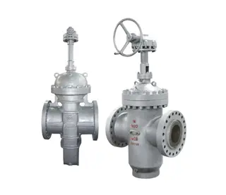
Valve body defects can also cause leakage, such as damaged sealing surfaces in ball valves, deformed linings in fluorine-lined or rubber-lined butterfly valves, ruptured rubber diaphragms in diaphragm valves, or scratched sealing surfaces and jammed transmission components in gate valves.
5. Valve Oscillation and Noise
Valve oscillation is characterized by frequent up-and-down movement of the valve core accompanied by impact sounds, significantly reducing service life. Major causes include:
Insufficient spring stiffness leading to unstable output signals
Resonance caused by matching natural valve frequency with system frequency
Severe pipeline or foundation vibration transmitted to the valve
Operation at small openings where flow resistance, velocity, and pressure fluctuate sharply, exceeding valve stiffness
Cavitation can also generate noise. When the pressure differential before and after the valve is too large, local flow velocity increases and cavitation occurs, eroding the valve core and seat while producing noise.
Selecting an excessively large flow coefficient (Cv) often forces the valve to operate at small openings for extended periods, making it a common design cause of oscillation and noise.
Diagnostic Methods for Pneumatic Ball Valve Failures
Blind disassembly when faults occur is often inefficient and may even cause secondary damage. Establishing a systematic diagnostic process enables fast and accurate identification of root causes.
1. Systematic Inspection Procedure
A structured workflow should be followed:
Check the air supply system: Confirm compressor operation, inspect air tank pressure, regulator settings, and pipeline leakage.
Inspect the control circuit: Measure solenoid coil voltage and verify circuit continuity.
Examine the actuator: Observe whether the cylinder operates smoothly and listen for air leaks.
Check the valve body: Manually operate the valve to feel resistance and inspect packing tightness.
2. Targeted Corrective Measures
Air supply faults: Adjust the filter regulator to the rated pressure (typically 0.4–0.6 MPa) and replace filter elements if necessary. Repair leaking pipelines promptly.
Blocked solenoid valves: Remove and clean the spool and seat; replace severely worn units. If the coil is burned out, confirm resistance values and ensure voltage and power ratings match during replacement.
Cylinder air leaks: Usually caused by aged O-rings—disassemble and replace seals. Blow out or replace clogged speed controllers. Replace weakened springs.
Emergency treatment for sticking valves: Quickly open and close bypass valves to flush away debris with medium flow, or grip the valve stem with a pipe wrench and rotate it back and forth under external signal pressure to help the core pass the obstruction. If ineffective, slightly increase air pressure and repeat the action. Persistent problems require dismantling.
Packing leakage treatment: Adjust gland bolt tightness evenly and symmetrically. Replace aged packing with flexible graphite packing, which offers excellent airtightness, low friction, high-temperature resistance, corrosion resistance, and long service life.
Internal leakage treatment: Adjust the valve stem length, polish sealing surfaces with fine sandpaper to remove scratches, and replace severely damaged valve core and seat assemblies. Maintain sealing surface precision during lapping to avoid damaging the sealing line.
3. Eliminating Oscillation and Noise
Minor vibration can be addressed by increasing valve stiffness, such as adopting higher-stiffness springs or piston actuators. Pipeline vibration should be mitigated by reinforcing supports and removing vibration sources.
Resonance problems can be solved by replacing the valve with a different structure or modifying pipeline layout to adjust frequency matching. Oscillation caused by small-opening operation requires reselection, choose a valve with a smaller Cv or adopt split-range control or parallel valve configurations to expand the controllable range.
Maintenance of Pneumatic Ball Valves
Regular maintenance is essential for preventing failures and extending valve service life. A comprehensive maintenance system is recommended.
1. Daily Inspection
Conduct routine checks to ensure correct valve switching status and absence of abnormal movement. Verify stable air pressure, inspect pipelines for leaks, and watch for unusual noise or vibration.
2. Periodic Maintenance
Monthly: Clean surface dust and oil, and check bolt tightness.
Quarterly: Inspect stuffing box leakage, adjust the gland, examine cylinder O-rings, test solenoid directional performance, and verify speed controller settings.
Semiannually: Conduct a full inspection of seal wear and lubricate moving parts.
Annually: Disassemble the valve for inspection, remove internal deposits, measure sealing clearances, and replace aged seals.
3. Seasonal Maintenance
Before winter, inspect insulation and heat tracing systems to prevent freezing. During high-temperature seasons, verify the heat resistance of packing and seals. In rainy periods, implement moisture-proofing and anti-corrosion measures.
4. Establish Maintenance Records
Document each maintenance activity, including dates, tasks performed, replaced components, and responsible personnel. Track valves with frequent failures, analyze patterns, and implement preventive measures.
Conclusion
The reliable operation of pneumatic ball valves is directly related to the safety and stability of the entire process system. By thoroughly understanding their working principles, mastering diagnostic techniques for common faults, and establishing a scientific maintenance system, failure rates can be significantly reduced and service life extended.
It is important to emphasize that complex faults or situations requiring disassembly must be handled by professional technicians. Blind dismantling should be avoided to prevent greater losses. With the development of intelligent diagnostic technologies, pneumatic ball valve maintenance will become increasingly convenient and efficient, but solid theoretical knowledge and practical experience will always remain essential skills for technical personnel.
Send your message to this supplier
Related Articles from the Supplier
Guide to Troubleshooting of Pneumatic Ball Valves
- Feb 04, 2026
Guide to Key Steps of Safety Valve Adjustment
- Oct 09, 2025
Guide to Valve Performance and Selection
- Oct 10, 2025
Guide to Valve Electric Actuator Selection
- Nov 05, 2025
Guide to Diaphragm Pump Material Selection
- Dec 19, 2025
Related Articles from China Manufacturers


Guide to Liquid Die Forging Technology
- May 20, 2025

Guide to Nickel-Based Alloy Open Die Forging
- Dec 09, 2025
Guide to Multi-Directional Die Forging Technology
- Feb 04, 2026
Guide to Metal Forging with Presses
- Mar 17, 2026


Guide to Non-Ferrous Metal Forging Process
- Nov 06, 2025
Related Products Mentioned in the Article
Zhejiang Kosen Valve Co., Ltd.
- https://www.kosenvalve.com/
- Business Type: Industry & Trading, Manufacturer,
Supplier Website
Source: https://www.kosenvalve.com/media-hub/guide-to-troubleshooting-of-pneumatic-ball-valves.html