Guide to Electric Ball Valve Troubleshooting and Maintenance
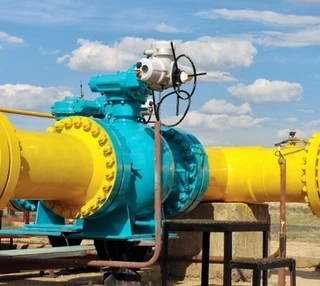
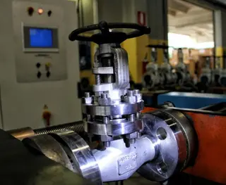
Electric ball valves are essential control devices in fluid handling systems. From home heating networks to large-scale chemical plants, these valves are responsible for starting, stopping, or regulating the flow of liquids and gases within pipelines. Their operation relies on an electrically driven ball with a bore that rotates to open or close the valve. When the bore aligns with the pipeline, the valve opens; when perpendicular, the valve closes.
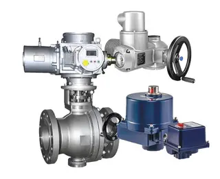
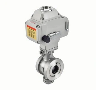
A typical electric ball valve consists of four main components: the valve body, actuator, ball, and seals. Due to prolonged exposure to pressure, friction, and fluid erosion, electric ball valves are prone to various operational issues. Understanding common faults, their symptoms, causes, and troubleshooting methods enables operators to restore normal operation quickly. Establishing a preventive maintenance schedule can further extend valve lifespan and reduce downtime caused by unexpected failures. This guide provides a detailed overview of common electric ball valve faults, diagnostic methods, and maintenance strategies.
Principle and Structure of Electric Ball Valves
Electric ball valves are crucial devices in fluid control systems, widely applied in both home automation and industrial environments. They operate by rotating an internally bored ball using an electric motor to control the flow of liquids or gases. When the ball’s bore aligns with the pipeline, the valve fully opens, allowing fluid to pass freely. When the ball rotates 90 degrees, the bore becomes perpendicular to the pipeline, fully closing the valve and blocking fluid flow.
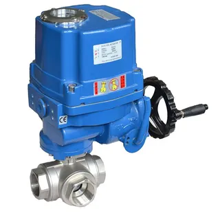
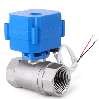
The main components of an electric ball valve include:
- Valve Body: Serves as the housing, designed to withstand internal pipeline pressure.
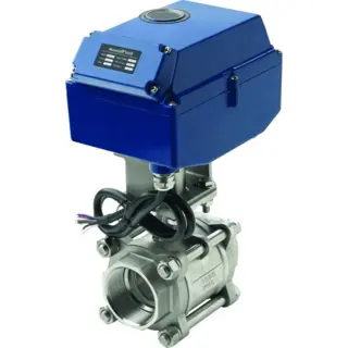
- Actuator: Combines an electric motor and gear reduction mechanism, providing rotational force.
- Ball: A spherical component with a circular bore that opens or closes the flow path.
- Seals: Ensure tight closure, preventing leakage when the valve is shut.
These components work in unison to deliver precise and reliable flow control. Over time, however, mechanical wear, media corrosion, and environmental factors can lead to operational faults.
Common Faults and Troubleshooting Methods
Like all mechanical equipment, electric ball valves may experience issues during operation. Understanding how to identify and resolve common faults helps maintain system reliability.
1. Valve Fails to Open or Close
One of the most frequent problems is the inability of the valve to operate. Troubleshooting should focus on the following areas:
- Power Supply and Wiring Issues: Begin by verifying that the valve receives proper power and that the voltage matches the rated value. Check for loose or corroded terminals to ensure secure connections. For valves controlled by a controller, confirm that the controller is sending the correct open/close signals.
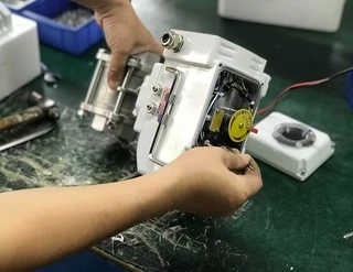
- Actuator Malfunction: If power is normal but the valve remains unresponsive, the actuator may be faulty. Listen for unusual sounds, such as clicking or grinding, when attempting operation. A damaged actuator typically requires complete replacement.
- Internal Obstructions: Debris, welding slag, or scale inside the pipeline can become lodged between the ball and seat, preventing full opening or closure. Disassemble the valve to remove obstructions and consider installing a filter upstream to prevent recurrence.
2. Slow or Unstable Valve Movement
If the valve operates sluggishly or irregularly, the causes may include:
- Insufficient Voltage: Low supply voltage reduces motor torque, slowing operation. Use a multimeter to check actuator terminal voltage and compare it with the nameplate rating to identify voltage drop issues.
- Inadequate Lubrication: Friction increases when gears and bearings inside the actuator are under-lubricated, resulting in slower movement. Follow manufacturer-recommended lubrication schedules and use approved lubricants.
- Electromagnetic Interference (EMI): Nearby high-power devices or variable frequency drives can disturb the valve control circuitry. Use shielded cables or relocate the valve away from interference sources.
- Component Wear: Over time, gears, bearings, and stems can wear, reducing transmission efficiency. Replace worn components as needed.
3. Valve Leakage or Sealing Problems
Leakage can occur externally or internally. External leakage refers to fluid escaping from the valve body or connections, while internal leakage occurs when fluid flows past a closed valve.
- Worn Seals: Seat seals on both sides of the ball can wear or harden over time. Inspect for cracks, deformation, or hardening and replace with identical specifications if damaged.
- Loose Connections: Flange or threaded connections between the valve and pipeline may loosen due to vibration. Retighten bolts using a torque wrench in the proper sequence.
- Excessive Pressure: System pressure exceeding the valve’s rated limit can compromise sealing. Verify system pressure against the valve’s pressure rating and, if necessary, install a pressure-reducing valve or upgrade to a higher-pressure valve.
- Improper Installation: Misalignment between the valve and pipeline can induce bending or torsional stress, damaging seals. Ensure correct alignment and tighten bolts diagonally and evenly.
4. Valve Overheating
If the actuator casing becomes unusually hot, possible causes include:
- Overload Operation: The valve may be undersized, operating near its maximum torque limit. Verify operating torque versus the rated actuator torque and replace with a larger actuator if needed.
- Poor Ventilation: Valves installed in enclosed or high-temperature areas may overheat due to insufficient heat dissipation. Improve ventilation or add forced air cooling.
- Thermostat Failure: Some actuators include a thermostat for overheat protection. A failed thermostat can allow continuous motor operation, causing overheating. Test for proper function and replace if defective.
Advanced Diagnostic Techniques
Complex or intermittent faults may require systematic diagnostic methods and specialized tools.
- Electrical Testing: Use a multimeter to measure circuit continuity and voltage. Inspect every wire from the controller to the actuator for open or short circuits. Measure motor winding resistance to detect shorted or open coils.
- Control Signal Testing: For valves using analog signals (e.g., 4–20 mA), measure the signal loop current to ensure it matches the control command. Check for interference and confirm proper grounding of shielding.
- Visual Inspection: Regularly examine the valve and surrounding components for wear, corrosion, rust, or leakage. Pay particular attention to stem-actuator connections and cable entry seals, which are prone to failure.
- Comparative Analysis: When replacing parts, compare old and new components for differences in size, wear patterns, and surface condition. This helps identify whether issues are due to normal wear or abnormal damage.
Preventive Maintenance Measures
Preventive maintenance cannot fix existing faults but can significantly reduce the risk of future failures.
- Regular Inspection and Cleaning: Establish inspection intervals based on operating conditions. Industrial valves may require monthly checks, while residential systems may suffice quarterly. Focus on cleaning dust and oil from the valve body to prevent contamination entering the actuator.
- Install Y-Strainers: Installing a Y-strainer upstream of the electric ball valve can intercept solid particles, welding slag, and debris, protecting the ball and seals. Choose mesh size according to fluid cleanliness, typically 40–60 mesh.
- Follow Installation Guidelines: Carefully review the manufacturer’s technical manual before installation. Ensure valve flow direction matches pipeline flow, actuator alignment is precise, and cable specifications meet current requirements.
- Develop a Maintenance Schedule: Maintain detailed records, including inspection dates, valve condition, replaced parts, and test results. Critical industrial valves may require monthly inspections, whereas residential valves may be maintained quarterly or biannually.
- Proactive Replacement of Wear Parts: Seals, packing, electrical contacts, and other wear components should be replaced before failure. Maintain a secure stock of critical spare parts to ensure rapid response.
Systematic Analysis of Fault Causes
Most electric ball valve failures develop gradually rather than occurring suddenly.
- Voltage Instability: Frequent voltage fluctuations can overheat the motor, accelerate insulation aging, and eventually burn out the motor. Use a regulated or uninterruptible power supply for critical valves.
- Media Contamination: Particles, rust, or microorganisms in water can deposit on the ball and seat, increasing friction and wear. In addition to filters, periodically flush pipelines.
- Improper Installation: Tightening the valve body with a standard wrench instead of designated hex points can deform the valve. Loose cable glands can allow moisture and dust into the actuator.
- Environmental Factors: Outdoor valves exposed to sunlight and rain experience accelerated seal aging. In cold environments, residual water inside the valve may freeze, causing cracks. Protective covers and heat tracing can mitigate these risks.
Conclusion
Electric ball valves are durable and reliable components in fluid control systems, but proper use and regular maintenance are crucial for maximizing service life. Understanding common fault symptoms and troubleshooting procedures enables rapid identification and resolution of issues. Routine visual inspections, cleaning, and record-keeping allow early detection of potential problems, preventing unexpected production interruptions.
For critical valves, establish a systematic maintenance plan that includes periodic lubrication, torque monitoring, and proactive replacement of wear parts. Through scientific maintenance management, electric ball valves can deliver stable, reliable operation throughout their design lifespan, ensuring efficiency and safety across residential and industrial applications.
Send your message to this supplier
Related Articles from the Supplier
Guide to Valve Electric Actuator Selection
- Nov 05, 2025
Guide to Key Steps of Safety Valve Adjustment
- Oct 09, 2025
Guide to Valve Performance and Selection
- Oct 10, 2025
Guide to Diaphragm Pump Material Selection
- Dec 19, 2025
Guide to Industrial Valve Pressure Testing
- Jan 14, 2026
Related Articles from China Manufacturers
Related Products Mentioned in the Article
Zhejiang Kosen Valve Co., Ltd.
- https://www.kosenvalve.com/
- Business Type: Industry & Trading, Manufacturer,
Supplier Website
Source: https://www.kosenvalve.com/media-hub/guide-to-electric-ball-valve-troubleshooting-and-maintenance.html