Guide to Butterfly Valve Installation Direction
As one of the most widely used valve types in industrial piping systems, butterfly valves directly affect the operating efficiency and service life of the entire system. In practical work, many engineering technicians encounter a key question: Can a butterfly valve be installed upside down? What are the requirements for medium flow direction during installation? This article, from a practical application perspective, provides detailed answers to these questions and offers a complete installation operation guide.
Core Issues of Butterfly Valve Installation Direction
In industrial piping systems, the installation quality of butterfly valves directly determines the operating efficiency of the entire pipeline network and the service life of equipment. According to statistics, nearly 40% of valve failures originate from improper installation, among which incorrect installation direction is one of the most common yet easily overlooked problems. Whether for new construction projects or equipment retrofits, technicians must first clarify: what elements are included in the installation direction of a butterfly valve? What consequences will different orientation choices bring? The answers to these questions are the prerequisite for ensuring the smooth progress of subsequent installation work.
1. What Is the Installation Direction of a Butterfly Valve?
The installation direction of a butterfly valve refers to the orientation of the valve when installed in a piping system. This includes two aspects: first, the orientation of the valve stem (horizontal or vertical); second, the flow direction of the medium inside the valve body (from top to bottom or from bottom to top). Correct installation direction not only ensures normal opening and closing of the valve but also extends the service life of sealing components and reduces operating torque.
In practical engineering, the selection of installation direction for a butterfly valve must comprehensively consider factors such as pipeline layout, operating space, medium characteristics, and maintenance convenience. Understanding these basic requirements is the first step in ensuring installation quality.
2. Can Butterfly Valves Be Installed Vertically?
Butterfly valves can be installed vertically, but specific conditions must be met. During vertical installation, the disc should remain in a horizontal state when performing opening and closing actions, and the valve stem should be vertically aligned. This installation method is usually applied in the following scenarios:
- The pipeline system is arranged vertically, and horizontal installation space is insufficient
- Special working conditions require gravity assistance to help close the valve
- Equipment layout limitations require vertical installation
Special attention must be paid to medium flow direction during vertical installation. When the medium flows from bottom to top, gravity acts in the same direction as the closing action, helping the valve close more easily and reducing operating force. Conversely, if the medium flows from top to bottom, gravity becomes a resistance force, requiring greater operating force to close the valve. Long-term operation under such conditions may accelerate actuator wear.
3. Why Horizontal Installation Is More Recommended?
Although vertical installation is unavoidable in certain cases, horizontal installation remains the optimal choice for butterfly valves. In horizontal installation configuration, the valve stem remains in a horizontal position, and the disc completes opening and closing actions within a vertical plane. The advantages of this layout are reflected in the following aspects:
- Operational Convenience: The handle or actuator is located on the side, allowing operators to conveniently perform manual operation or maintenance without climbing or special tools.
- Gravity Assistance: When closing the valve, the torque generated by the disc’s own weight helps sealing, which is particularly evident in large-diameter valves.
- Maintenance Friendliness: When the valve stem is placed horizontally, wear at the packing seal area is more uniform, leakage risk is reduced, and routine maintenance becomes more convenient.
- Debris Protection: A horizontal valve stem reduces the possibility of impurity accumulation in the sealing area, which is especially important for media containing solid particles.
Preparatory Work Before Butterfly Valve Installation
After clarifying the selection principles for installation direction, preparatory work before actual operation must not be overlooked. Adequate preparation not only improves installation efficiency but also prevents rework and potential hazards from the source. According to statistics, standardized preliminary preparation can increase the one-time installation qualification rate by more than 60%, significantly reducing leakage and sticking problems during later commissioning. Preparation work mainly revolves around three aspects: valve and accessory inspection, pipeline system cleaning, and tool and material preparation.
1. Valve and Accessory Inspection
Pre-installation inspection directly affects subsequent construction quality. First, verify whether the valve model and specifications match the pipeline design parameters, focusing on confirming nominal diameter, nominal pressure, applicable medium, and temperature range. Carefully inspect the valve body appearance for sand holes or cracks, check whether the sealing ring is intact without aging, and ensure bolts and other fasteners are complete.
For resilient seated butterfly valves, such products usually adopt an integral rubber lining design, and the sealing surface is directly formed inside the valve body. No additional gasket is required during installation. For high-performance butterfly valves or metal hard-sealed valves, due to their application in high-pressure and high-temperature conditions, appropriate gaskets must be equipped to ensure sealing reliability.
2. Pipeline System Cleaning
The cleanliness of the pipeline interior is a key factor in ensuring sealing performance. Thoroughly remove welding slag, rust, oil stains, and dust inside and outside the pipeline. Pay particular attention to the flange sealing surfaces, ensuring they are flat and free of burrs. Any residual foreign matter may cause sealing surface damage or leakage.
Check the spacing of pipeline flanges. It should be 3/16 inch (approximately 4.76 mm) wider than the face-to-face dimension of the valve. This gap provides necessary adjustment space for valve installation, preventing flange over-tightening from compressing the valve body and causing deformation, and also avoiding damage to the sealing surface due to excessive squeezing.
3. Tool and Material Preparation
Prepare corresponding tools according to the connection method: clamp-type connections require specialized clamp wrenches; flange connections require torque wrenches, levels, and gaskets. It is recommended to prepare sealant compatible with the medium characteristics as a backup. For gear-operated valves, hex wrenches should also be prepared for subsequent adjustments.
Control the ambient temperature within the range of -20°C to 80°C. Exceeding this range may affect the physical properties of rubber sealing components. When working in extreme temperature environments, preheating or insulation measures should be taken.
Detailed Steps for Butterfly Valve Installation Operation
After completing preliminary preparations, the installation construction phase formally begins. Butterfly valve installation requires high precision. Any negligence in any step may result in sealing failure or operational malfunction. The following steps are compiled according to GB/T 12238 standards and engineering practice experience and are applicable to both flange connection and clamp connection, the two mainstream connection methods. Installation personnel should strictly follow the sequence without skipping or omitting steps.
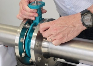
1. Valve Positioning and Alignment
Place the valve at the predetermined position between the two flanges, ensuring the valve stem direction is convenient for operation. Use a level to check the coaxiality between the valve and the pipeline. According to GB/T 12238 standards, deviation should be controlled within 2 mm. Inaccurate alignment is one of the main causes of early valve failure. A few minutes of careful adjustment can prevent significant maintenance costs in the future.
Pay special attention to the disc position. Before flange tightening, manually rotate the disc to confirm that it can rotate freely without interfering with the pipe wall. Because butterfly valves have short structural lengths, the disc extends into adjacent pipelines, and collision risk must be eliminated.
2. Flow Direction Mark Confirmation
Some butterfly valve bodies are cast with medium flow direction arrows. During installation, ensure that the arrow direction is consistent with the pipeline medium flow direction. Although most modern butterfly valves are designed for bidirectional sealing, certain special structures (such as triple-offset butterfly valves) have a preferred flow direction. Reverse flow may increase wear or affect sealing performance.
For flow regulation applications, flow direction selection is even more important. The flow characteristic of butterfly valves is parabolic. When the opening angle is above 60° or below 15°, flow change is not sensitive to opening adjustment. Proper flow direction arrangement can optimize regulation performance.
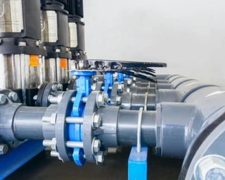
3. Flange Connection Tightening Process
When using flange connection, follow the steps below:
- Gasket Installation: Place a gasket compatible with the medium characteristics accurately at the center of the flange sealing surface, ensuring the inner diameter does not protrude into the pipeline to obstruct disc movement.
- Preliminary Positioning: Hand-tighten all bolts to basically fix the valve. Keep the valve in a half-open position at this time to avoid contact between the disc and flange inner diameter.
- Symmetrical Tightening: Use a torque wrench to tighten bolts gradually in 2–3 stages according to diagonal sequence (cross pattern method). After each tightening stage, check whether the valve center position has shifted. The final torque value should meet design specifications to ensure uniform sealing.
- Gap Verification: During tightening, gradually release the flange spreader and confirm that the valve remains centered between flanges without tilt or distortion.
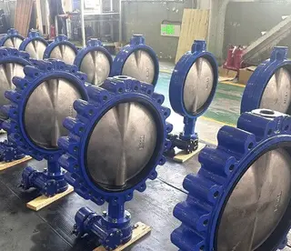
4. Clamp-Type Connection Operation
For clamp-connected butterfly valves, the operation is relatively simple:
Align the valve clamp interface with the pipeline clamp, ensuring the sealing groove is fully matched. Tighten bolts symmetrically. It is recommended to control torque within the range of 25–30 N·m. Specific values should follow the manufacturer’s manual. Over-tightening may damage the clamp or sealing ring, while insufficient tightening will result in leakage.
Post-Installation Commissioning and Inspection
Completion of installation does not mean the end of work. System commissioning and inspection are critical steps for verifying installation quality and identifying potential issues. Standardized inspection procedures can eliminate hidden risks in time and prevent operation with faults.
1. Operational Flexibility Test
After installation, slowly open the valve to the fully open position and confirm that disc movement is free of sticking and does not contact the pipeline or flange. Manually operate the handle through a 90° rotation and feel whether torque is uniform. Under normal conditions, opening and closing should be smooth without abnormal noise.
Open and close the valve 3–5 times repeatedly and observe whether there are wear marks on the sealing surface and leakage at the stem packing. For gear-operated valves, check whether clockwise rotation of the handwheel or control rod corresponds to closing action.
2. Pressure Testing Specifications
When conducting system pressure testing, it is strictly prohibited to pressurize the valve in a fully closed state. This will cause deformation and damage to the sealing ring due to one-sided pressure. The correct practice is to open the valve to a half-open position and slowly introduce the test medium (water or air).
Raise the test pressure to 1.5 times the working pressure (not exceeding the valve’s rated pressure) and maintain pressure for 5 minutes. Check for leakage at flange connections and stem sealing areas. If leakage is found, increase bolt torque appropriately in diagonal sequence or check whether the gasket is suitable.
3. Special Adjustment Methods
For lever-type butterfly valves, if the disc is not perpendicular to the pipeline axis in the closed position, adjustment is required:
- Loosen the top plate fixing bolts (usually two)
- Rotate the control rod counterclockwise until the disc is centered and perpendicular to both end flanges
- Retighten the top plate bolts
Gear-operated valves are adjusted through side hex bolts. Insert and remove the disc to check alignment. If necessary, repeat the adjustment process until smooth operation is achieved.
Common Installation Errors and Prevention
- Improper Gasket Usage: Using external gaskets for resilient seated valves is a common mistake, leading to excessive sealing compression and sharp increases in operating torque. Omitting gaskets for metal hard-sealed valves will inevitably cause leakage. The sealing method must be selected correctly according to valve type.
- Incorrect Bolt Tightening Sequence: Failure to tighten in diagonal order leads to uneven flange surface stress, valve body deformation, and disc jamming. The cross-pattern method must be strictly followed with staged and uniform torque loading.
- Ignoring Flow Direction Marks: Although most butterfly valves are bidirectional, optimized one-way designs installed in reverse will increase operating torque by 10%–30% and accelerate seal wear. Developing the habit of confirming flow direction is crucial.
- Insufficient Environmental Adaptation: Installing directly in environments outside the -20°C to 80°C range without protective measures will cause rubber sealing components to harden or soften, leading to leakage in a short time.
Maintenance Recommendations
Regularly check bolt tightening status, especially under conditions with large temperature fluctuations, where metal creep may reduce preload. Keep the valve stem packing area clean and replenish or replace packing in time. For valves not operated for long periods, it is recommended to actuate them once every quarter to prevent sealing surface adhesion.
Record operating torque values during each maintenance session. A significant increase in torque often indicates sealing surface wear or impurity intrusion, requiring timely inspection and repair.
By following the above installation guidelines, butterfly valves can achieve optimal performance in pipeline systems and realize long-term reliable operation. Proper installation direction selection, meticulous construction processes, and regular maintenance inspections are the foundation for ensuring safe and efficient operation of industrial piping systems.
Send your message to this supplier
Related Articles from the Supplier
Guide to Butterfly Valve Installation Direction
- Feb 24, 2026
Guide to Soft Seal Butterfly Valves
- Jan 16, 2026
Guide to Key Steps of Safety Valve Adjustment
- Oct 09, 2025
Guide to Valve Performance and Selection
- Oct 10, 2025
Guide to Valve Electric Actuator Selection
- Nov 05, 2025
Guide to Diaphragm Pump Material Selection
- Dec 19, 2025
Related Articles from China Manufacturers
Guide to Butterfly Valve Sealing Principles
- Nov 27, 2025

Quick Guide to Butterfly Valve Seal Replacement
- Apr 10, 2024
Related Products Mentioned in the Article
Zhejiang Kosen Valve Co., Ltd.
- https://www.kosenvalve.com/
- Business Type: Industry & Trading, Manufacturer,
Supplier Website
Source: https://www.kosenvalve.com/media-hub/guide-to-butterfly-valve-installation-direction.html