What is the Use of Extended Bonnet in Cryogenic Valve
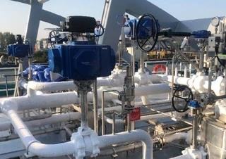
In the fields of petrochemicals, liquefied natural gas (LNG), and air separation equipment, handling extremely low-temperature liquid media is often required. Valves suitable for media temperatures between -40°C and -196°C are collectively referred to in the industry as cryogenic valves. The media handled by these valves include liquefied natural gas (LNG), liquid oxygen, liquid hydrogen, ethylene, liquefied petroleum gas, and others. These media are not only flammable and explosive, but during warming, they can vaporize and expand hundreds of times in volume, placing extremely high demands on valve safety and sealing performance.
Common cryogenic valve types include low-temperature emergency shut-off valves, low-temperature globe valves, low-temperature check valves, LNG-specific cryogenic valves, and natural gas-specific cryogenic valves. They are widely used in large-scale chemical projects, such as 300,000-ton ethylene plants and LNG storage and transportation systems.
Extended Bonnet: The Defining Feature of Cryogenic Valves
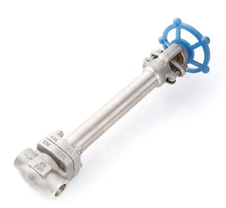
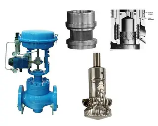
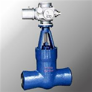
Careful observation of cryogenic valves reveals the most obvious difference from ordinary valves: their bonnets feature a slender, neck-like structure, called the extended bonnet. This design is not for aesthetics but is a core structural element designed for functional requirements under cryogenic conditions. The extended bonnet increases the length of the valve bonnet, positioning the packing chamber (i.e., the valve stem sealing area) away from the extremely cold media inside the valve body. This structure creates a relatively stable cavity beneath the bonnet, allowing the valve handle and sealing components to operate in an environment close to ambient temperature.
Core Functions of the Extended Bonnet
The extended bonnet has become a standard configuration for cryogenic valves due to multiple engineering requirements, not a single factor. From operational safety to sealing assurance, insulation construction, and maintenance convenience, this structural design addresses a series of problems under low-temperature conditions. Specifically, the core functions of the extended bonnet are reflected in the following four key aspects.
1. Protecting Operator Safety
If the valve handle directly contacts the low-temperature region, at -100°C or even lower, operators can easily suffer frostbite when operating by hand. The extended bonnet raises the handle position, keeping it away from the low-temperature zone, fundamentally eliminating this safety hazard.
2. Ensuring Proper Operating Temperature for the Packing Chamber
This is the most important function of the extended bonnet. The sealing performance of the valve packing chamber directly determines whether the valve will leak, and low temperatures greatly affect packing performance:
Mechanism of low-temperature impact on packing performance:
As temperature decreases, the elasticity of the packing material gradually disappears, reducing sealing effectiveness. When the temperature is too low, if media leakage occurs, the leaking media can freeze in the gap between the stem and packing. Freezing causes three serious consequences:
The ice layer can jam the valve stem, preventing normal operation.
Forced operation will scratch the frozen packing, causing permanent damage.
Damaged packing can lead to serious leakage, not only causing media loss but also destroying insulation, causing liquefied gas vaporization, and even triggering safety incidents.
Through the extended bonnet structure, the packing chamber temperature can be maintained above 8°C, ensuring the packing retains normal elasticity and sealing performance, fundamentally avoiding the above problems.
3. Facilitating Insulation Construction and Maintenance
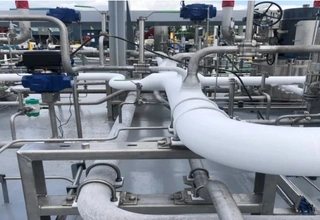
Cryogenic pipelines generally require thick insulation layers to prevent heat loss. The extended bonnet design fully considers the practical requirements of insulation construction:
- Convenient insulation wrapping: The extended structure provides sufficient space for wrapping insulation materials, ensuring the insulation layer fully covers key valve components and effectively prevents heat loss.
- Easy maintenance: The packing gland is located outside the insulation layer, allowing direct operation for tightening gland bolts or adding packing without destroying the insulation layer. This greatly reduces maintenance costs and prevents energy loss caused by insulation damage during maintenance.
- Length matching requirements: When determining the length of the extended bonnet, in addition to meeting BS standards, MSS SP standards, and special requirements from the design unit, the thickness of the designed insulation layer must also be considered. If the insulation layer is thicker than the bonnet, the bonnet should be extended to match the insulation thickness, ensuring full insulation coverage.
4. Enabling Quick Replacement of Valve Internals
In cryogenic process systems, valves are often installed together with piping inside a cold box. The extended bonnet can pass through the cold box wall and extend to the outside. This design offers significant maintenance convenience:
Internal components can be replaced by removing only the bonnet, without dismantling the valve body welded to the pipeline.
This minimizes cold box openings, reduces leakage risks, maintains system sealing, and significantly shortens maintenance time and costs.
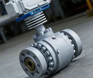
Special Installation Requirements for Cryogenic Ball Valves
Due to structural particularities, cryogenic ball valves must strictly follow specific directional requirements during installation; otherwise, their performance will be seriously affected, and safety incidents or economic losses may occur.
1. Prohibition of Horizontal Installation (Stem-Up Principle)
Cryogenic ball valves must never be installed horizontally; the valve stem must always point upward. This is dictated by the extended bonnet structure:
If the stem is horizontal, the extended portion of the bonnet will be filled with cryogenic media, causing two severe consequences: sealing failure of the valve and direct transmission of cold to the valve handle, potentially causing frostbite.
The correct installation method is stem-up, so that the cavity beneath the bonnet can accumulate stationary gas, forming an effective temperature gradient that blocks cold transfer upward.
2. Determining the Pressure-Relief Direction
Cryogenic ball valves typically have a pressure-relief structure on the upstream side. It is important to note that “upstream” here does not always mean opposite to the pipeline flow. When the valve is closed, the pressure-relief direction should point to the true upstream side.
Practical application example: In control valve maintenance, shut-off valves are installed at both ends of the control valve. These shut-off valves should be installed in opposite directions, with each pressure-relief direction opposite to the control valve direction. When both shut-off valves are closed for maintenance, the pressure inside the valve chamber can be released toward the connected pipeline. Incorrect direction would cause gas leakage into the atmosphere, leading to environmental pollution and explosion hazards. Therefore, pressure-relief directions must be clearly marked on the process flow diagram and accurately reflected on the pipeline isometric drawing.
Stem Orientations for Different Temperature Ranges
The valve stem orientation is not universally required to be vertical but must be determined based on the specific operating temperature. Although no unified international standard exists, industry engineering practice has formed a set of reference technical specifications:
- Operating Temperatures Above -20°C: For temperatures below 0°C but not lower than -20°C, general valve structures may be used, and stem direction is unrestricted. In this temperature range, ordinary valve sealing structures can still function normally without specialized cryogenic design.
- Operating Temperatures Between -20°C and -73°C: For this range, the stem must be upward, with an angle no greater than 60° from vertical. This angle ensures the formation of an effective gas insulation layer beneath the bonnet, blocking cold transfer.
- Deep Cryogenic Conditions Below -73°C: For temperatures below -73°C, the stem must be upward, with an angle no greater than 30° from vertical. Lower temperatures require a stricter vertical structure to ensure insulation effectiveness.
- Exceptions for Special Locations: Valves in stagnant areas are exempt from the above angle limitations, including: Valves at the root of pressure instruments mounted on the main pipeline top. Especially for low-temperature safety valve inlet shut-off valves, vertical installation on the riser is recommended, and the stem may be horizontal. These valves are infrequently operated and often have additional insulation or heating measures.
Factory Handling Requirements for Cryogenic Valves
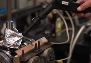
Since cryogenic valves operate at low temperatures, residual moisture can be extremely hazardous. Water inside the valve can freeze, expand, and damage internal components, causing sealing failure or structural damage.
- Strict Drying Process: After hydrostatic testing, valves must undergo thorough drying to remove all moisture from internal cavities and passages.
- Pneumatic Testing as an Alternative to Hydrostatic Testing: Considering limited construction site conditions, hydrostatic testing may not allow complete water removal and drying. Increasingly, cryogenic ball valves are pneumatically tested instead of hydrostatic testing. Although slightly more expensive, this effectively avoids residual moisture risk and ensures normal operation upon delivery.
Engineering Value of the Extended Bonnet
Although the extended bonnet increases valve height and material cost, its engineering value in cryogenic conditions is irreplaceable:
- Safety: Protects operators from frostbite and prevents leaks or explosions caused by sealing failure.
- Reliability: Maintains packing chamber at appropriate temperature, ensuring long-term sealing performance and avoiding ice-related operational failure.
- Economy: Facilitates insulation construction and maintenance, reduces heat loss and energy consumption, and allows quick replacement of valve internals, reducing downtime and maintenance costs.
- Compliance: Meets BS, MSS SP, and project-specific technical requirements, ensuring smooth project acceptance.
Conclusion
The extended bonnet design is the culmination of engineering wisdom from long-term practice. By adjusting simple geometric dimensions, it cleverly solves the complex problems of insulation, sealing, safety, and maintenance under cryogenic conditions. For professionals involved in cryogenic design, valve selection, installation, and operation, thoroughly understanding the extended bonnet design principles and technical requirements is the foundation for ensuring safe and efficient operation of low-temperature systems.
In practice, strict adherence to stem orientation according to temperature levels, correct bonnet length matching insulation thickness, clear pressure-relief marking, and thorough factory drying are essential. Only by implementing these details can the performance advantages of cryogenic valves be fully realized, ensuring long-term stable operation of the entire process system.
Send your message to this supplier
Related Articles from the Supplier
Related Articles from China Manufacturers

What Is the Cam Lock? How to Use it?
- Nov 15, 2022

What Is the Seamless Steel Pipe for
- Sep 16, 2013
What Is the Meaning of the Gate Valve Model?
- Jul 04, 2020
Related Products Mentioned in the Article


Supplier Website
Source: https://www.magpievalves.com/media-hub/what-is-the-use-of-extended-bonnet-in-cryogenic-valve.html