Industrial Valves: Basic Functions and Types of Valves
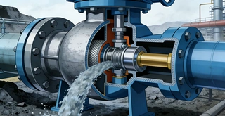
What is a valve? A valve is a component used to control the flow of liquid or gas (i.e. continuous and stable motion) to meet the ideal working conditions of a fluid system. This can be achieved by stopping, adjusting, or changing the flow direction of the fluid. When a liquid or gas flows, it will flow from places with higher pressure to places with lower pressure. Usually, the flow is measured by a flow meter and recorded as a distance or volume ratio per unit time (e.g. meters per second, gallons per day, liters per minute, etc.).
How do valves work? Valves allow fluid to pass through, and their flow rate depends on various factors, including the diameter of the valve end connection and the flow path of the valve. To help understand the ability of valves to control flow, manufacturers typically provide the valve with a flow coefficient, or CV. A higher CV value means a larger flow rate, but a higher CV value is not necessarily advantageous. Depending on the valve type and application, some valves may have a CV close to zero.
Small caliber fluid systems play an important role in ensuring efficient production and operation of global industrial enterprises, and valves play a critical role in the functional implementation of these systems.
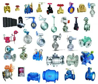
There are various types of valves for controlling flow, and the control methods are different. Therefore, fluid system operators must understand the existing valve types and the functions of different valves to ensure the selection of suitable valves for their respective application scenarios.
To choose the appropriate valve, fluid system designers and operators need to consider the following questions: "Do you need to stop and start fluid flow? Do you need to control the flow direction? Do you need to regulate flow? Do you need to protect the system from overpressure?" The answers to these questions will determine which type of valve is needed. On this basis, designers or operators can further consider more detailed valve selection factors to ensure that the selected valve meets its application requirements in terms of size, material, and performance standards.
In this article, we will explore the starting point for choosing the right valve: understanding the different types of valves used in industrial fluid systems so that you can find the valve functionality required for your application.
The basic knowledge of valve function
How to classify valves?
In industrial fluid systems, you need to understand the five main valve functions: switch control, flow regulation, flow control, overpressure protection, and overcurrent control. Each type has an industry standard symbol, commonly found in piping and instrumentation diagrams (P&IDs). Understanding the classification of valves and their corresponding symbols is very useful so that you can quickly associate the valve symbols in the P&ID with the functions of the valve types they represent.
Switch control. This is the basic type of valve function. The switch control valve is used to start or stop the flow of fluid. Although the functional nature of valves is relatively basic, there are many types of switch control valves available for selection. Examples include the following valves.
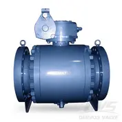
1. Ball valves: A handle is used to rotate the ball inside the valve to block or allow fluid to pass through the valve, thereby achieving reliable shut-off function.
2. Plug valves: The working principle of a plug valve is similar, except that it does not have a sphere. It blocks or allows fluid flow by rotating the valve plug inside the handle.
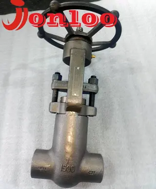
3. Bellows valves: The characteristic of bellows valve is that it has a high cylindrical valve stem with an extendable bellows installed on it. When the handle is rotated, the actuator is pressed onto the bellows, thereby precisely controlling the flow rate at a specific level.
4. Diaphragm valves: The working principle of a diaphragm valve is similar to that of a bellows valve, but it does not restrict flow by compressing the bellows on the valve stem with an actuator. Instead, it achieves flow restriction by pressing down a flexible diaphragm with the actuator.
Switching control valves play a crucial role in maintaining the safety of fluid systems. Many fluid handling processes are carried out in high-pressure, high-temperature environments, and some fluids may be hazardous, so preventing leaks to avoid risks to operators is crucial. Safely closing the valve in the event of a leak can help operators quickly cut off the flow of fluid. In P&ID, you can identify the switch control valve symbol (or ball valve symbol) by the bow tie shape.
Flow regulation. These types of valves help regulate the flow within the system, ranging from simple flow control to fine metering. Needle valves are commonly used to control or throttle flow. These valves precisely control the actuator inside the valve stem by rotating the handle, which ends with a needle tip that blocks the flow through the valve when it descends.
Similar to bellows valves or diaphragm valves, necessary timing valves can also achieve switching functions, but they are mainly used to control flow. These flow rates are determined by the orifice size, valve stem type, and valve stem position. As you can see, the flow control valve symbol (or needle valve symbol) in P&ID is similar to the switch control valve symbol, but with an additional downward triangle to indicate that the valve has flow control function.
Flow control. The function of this type of valve is to ensure that the fluid flows in the expected direction, and this type of valve can change the flow direction of the fluid in the system. Unidirectional valves and multi-way ball valves are commonly used for flow control. A one-way valve can prevent backflow and ensure that fluid flows continuously in only one direction. Multiport ball valves, like other ball valves, can achieve switch functions, but they allow operators to guide fluid flow in different directions according to the direction of the handle rotation.
Importantly, although flow control valves can provide a switch function when changing the flow direction, they cannot regulate the flow rate. In P&ID, you can find an icon with a downward sloping arrow between two lines to identify the flow control valve symbol (or one-way valve symbol).
Overpressure protection. This valve function can prevent the system pressure from exceeding the specified limit. Unloading valves and rupture discs are commonly used valve types here. In any system operating under pressure, pressure relief devices are crucial as they serve as the last line of defense against overpressure situations that may lead to explosions. The unloading valve can be calibrated to automatically open at a preset pressure level or gradually open as the pressure increases. Exhaust valves and purge valves can also be used to discharge, release, or empty fluids to ensure safe maintenance or operation of the fluid system.
If overpressure occurs, the overpressure protection valve helps to protect the safety of the factory while allowing production to continue. In P&ID, symbols with two intersecting triangles and antenna like structures above can be found to identify overpressure protection valve symbols (or safety valve symbols, etc.).
Overcurrent control. The overcurrent control valve can also play a role in system safety. When the flow rate through the valve increases to the preset value, the overcurrent control valve will activate, which helps to control the uncontrolled leakage of the system medium. If there is an overcurrent situation downstream, the lifting head of the valve will quickly move to the triggering position or fully forward position, preventing uncontrolled leakage of most system media and minimizing fluid escape as much as possible. When the pressure is balanced, the overcurrent control valve will reset.
The overcurrent control valve does not require a complex bypass mechanism and can also reduce maintenance time. In P&ID, the symbol for overcurrent control valve is as follows: a rectangle with a contracted portion on one side and a circle in the middle.
Send your message to this supplier
Related Articles from the Supplier

Related Articles from China Manufacturers
Industrial Valves in Stock for Fast Track Order
- Aug 13, 2024
Why Industrial Valves Fail and How to Repair
- Apr 20, 2020
Common Sealing Forms of Industrial Valves
- Jun 19, 2025
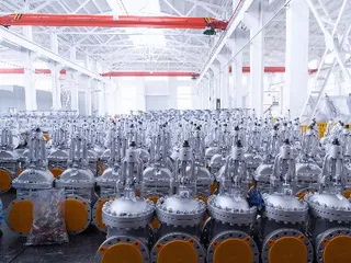
How Industrial Valves Are Manufactured
- Oct 13, 2024
Related Products Mentioned in the Article

Supplier Website
Source: https://www.landeevalve.com/industrial-valves-basic-functions-and-types-of-valves.html