How Pipe Deformation Affects Magnetic Flux Leakage (MFL) Detection: Case Study Analysis
Abstract: Based on the operating principle of the magnetic leakage detector (MLD), this paper clarifies the signal identification characteristics associated with pipe dents and bends. Using actual inspection data from a 711 mm natural gas pipeline as a case study, the signal characteristics of pipe bends exhibiting elliptical deformation are analyzed. Furthermore, based on the structural characteristics of the MLD and pipeline operating conditions, the risk factors that may lead to MLD blockage due to such deformation are systematically identified. Finally, field excavation confirmed the accuracy of the analytical results. Based on these findings, pipe replacement and repair effectively mitigated the risk of MLD blockage, providing valuable experience for subsequent geometric MLD data interpretation and the safe deployment of MLD tools.
Introduction
Pipeline transportation is a critical link connecting oil and gas production with consumption markets, playing a vital role in the energy system and serving as the lifeline of national energy security. In-service oil and gas pressure pipelines are prone to failure due to factors such as soil corrosion, stray currents, coating degradation, internal corrosion, material defects, delayed cracking, stress damage from external forces, natural disasters, and third-party interference. Due to the flammable, explosive, and highly polluting nature of the transported media, pipeline accidents can have extremely serious consequences.
Pipeline internal inspection enables the in-line detection of defects and other potential issues in long-distance oil and gas pipelines. It is an internationally recognized, efficient, and reliable method for defect detection and plays a vital role in ensuring safe pipeline operation. Pipeline internal inspection generally includes geometric inspection and magnetic flux leakage (MFL) inspection. Geometric internal inspection is typically performed after pipeline cleaning but before the MF (magnetic flux leakage) internal inspection. Its purpose is to check for pipeline deformations that could impede the passage of the MF inspection tool. MF internal inspection, on the other hand, is used to detect defects within the pipeline itself. For example, in a 711 mm diameter natural gas pipeline, the hot-bent sections have a bending radius of 6D. After routine cleaning, geometric internal inspection identified varying degrees of ovalization in several bends. Prior to the deployment of the magnetic flux leakage (MF) internal inspection tool, each of these deformed sections must be individually assessed to determine whether there is a risk of tool passage obstruction.
1. Structure and Detection Principle of the Geometric Internal Inspection Tool
The primary function of the geometric internal inspection tool is to detect geometric anomalies in the pipeline, such as dents, wrinkles, and ovalization. Pipes exhibiting deformation beyond a specified threshold may hinder the passage of magnetic flux leakage (MFL) inspection tools. By analyzing the data obtained from geometric internal inspection tools, it is possible to determine whether MFL inspection can be safely deployed and to identify additional deformation locations that may pose risks to pipeline integrity and operational safety. The deformation detection principle is based on a mechanical sensing mechanism in which a support arm in contact with the inner wall of the pipeline transmits wall deformation to an angular sensor, which then converts the mechanical displacement into a corresponding angular signal. This angular variation is subsequently converted into a linear displacement signal, which is then recorded and stored by the onboard data acquisition system. Depending on the pipeline diameter, multiple sensing units are evenly distributed around the circumference to ensure full coverage of the pipe wall. A typical structural configuration of a geometric internal inspection tool is shown in Figure 1.
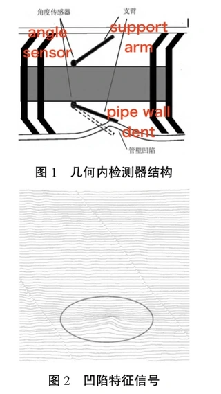
Figure 1: Geometric Internal Detector Structure
Figure 2: Depression Characteristic Signal
Generally, a dent is characterized by a localized inward deformation of the pipe wall caused by external loading. The corresponding signal characteristics obtained from the geometric internal inspection tool are shown in Figure 2. In Figure 2, multiple traces at the dent location exhibit an upward deviation. The magnitude of this upward displacement at each measuring point corresponds to the dent depth at the respective position along the pipeline wall. The point exhibiting the largest displacement change corresponds to the maximum dent depth. Based on the location and depth of the dent, data analysts evaluate the severity in accordance with relevant standards to determine whether repair or further mitigation measures are required. If the dent depth is sufficient to affect the passage of the magnetic flux leakage (MFL) inspection tool, immediate repair or pipe replacement is required before the MFL tool can be safely deployed for data acquisition. Due to its structural configuration, the geometric internal inspection tool generates distinct characteristic signals when passing through pipeline bends.
A schematic diagram of the geometric internal inspection tool passing through a bend is shown in Figure 3. During passage through the bend, the cups at both ends provide support, causing the geometric center of the tool to shift away from the pipeline centerline and move toward the intrados (inner side) of the bend. At this time, the sensor arms on the intrados (inner side) of the bend are compressed inward, while those on the extrados (outer side) expand outward. The corresponding measurement data indicate that the effective inner diameter of the pipe decreases on the intrados side, whereas it increases on the extrados side due to the geometric distortion induced by bending. The characteristic signals of the geometric internal inspection tool in a bend are shown in Figure 4. As illustrated, the bend direction is toward the left, and the signal exhibits an upward variation from the 6:00 to 12:00 position, with the maximum upward deviation occurring at approximately the 9:00 position. The signal exhibits a downward variation from the 12:00 to 6:00 position, with the maximum downward deviation occurring at approximately the 3:00 position. The location and deformation data are summarized in Table 1. All three deformation sections are located in in-plane bend pipes, with bend angles ranging from 45° to 90°.
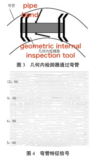
Figure 3 – Geometric ILI tool passing through a pipe bend
Figure 4 – Characteristic signal of the pipe bend
Table 1 Elliptical Deformation Data
|
No. |
Location (m) |
Ovalization (%OD) |
|
1 |
16719 |
20.5 |
|
2 |
30468 |
7.5 |
|
3 |
32286 |
17.3 |
The ovalization values of the three deformed sections are 20.5%, 17.3%, and 7.5%, respectively, and all deformation lengths exceed 2 m.
Note: Ovalization is defined as (maximum diameter − minimum diameter) / OD × 100%, where OD is the outer diameter of the pipe.
The elliptic deformation characteristic signal at 16,719 m is shown in Figure 5. This bend pipe turns left along the medium flow direction. In the figure, the signal curves on the outer side of the bend (1:00–4:00) and the inner side of the bend (7:00–11:00) shift upward, indicating a reduction in the internal diameter. The curves at the upper region of the bend (11:30–12:30) and the lower region (5:30–6:30) shift downward, indicating an increase in the internal diameter. A comparison of the deformed pipe cross-sections is shown in Figure 6. The solid lines in the figure represent the cross-sectional shape of the bend after deformation, showing the transformation from an initially circular geometry to an elliptical profile.
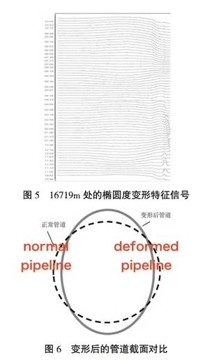
Figure 5: Ellipticity Deformation Characteristic Signal at 16719m
Figure 6: Comparison of Deformed Pipe Cross-Sections
3. Risk Analysis of Magnetic Leakage Detector Jamming
After identifying three regions of ovalization through geometric inspection, the next key step is to verify whether the pipeline satisfies the conditions for safe passage of the magnetic flux leakage (MFL) inspection tool. If deployment of a magnetic flux leakage (MFL) inspection tool is required, it is essential to ensure that the pipeline operating conditions will not lead to tool blockage or jamming during passage. If the pipeline deformation is confirmed to impede the passage of the magnetic flux leakage (MFL) inspection tool, timely communication with the operating unit is required to arrange for pipe replacement or repair before proceeding with inspection. Conventional magnetic flux leakage (MFL) inspection tools, by virtue of their operating principle, must incorporate two sets of permanent magnets, a magnetization circuit, and sensor probes in their structure to enable the detection of metal loss defects. Due to its more complex structural configuration, the magnetic flux leakage (MFL) inspection tool has lower passability within the pipeline compared to a geometric inspection tool. Specific passability parameters vary depending on the manufacturer and the tool specifications. When an MFL inspection tool traverses a standard bend, the drive cups at both ends deform under the constraint of the pipe wall, which increases frictional resistance during passage. At the same time, the magnetic brushes and sensor probes located in the central section of the tool, being closer to the pipe centerline, must undergo greater deformation to conform to the bend geometry, thereby significantly increasing frictional resistance against the pipe wall. A schematic diagram of the MFL internal inspection tool in a bend is shown in Figure 7.
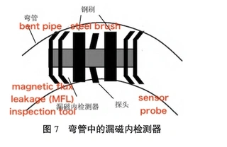
Figure 7: MFL internal detector in a bend
MFL internal inspection tools typically provide passability parameters for simple deformations in straight pipe sections. However, in bend sections—where tool attitude, pipe condition, and other influencing factors are more complex—precise passability parameters cannot be reliably defined (see Figure 8: Cross-sectional view of the MFL inspection tool at a bend with deformation). When an MFL internal inspection tool passes through a bend with ovalization, three adverse factors influence its passability.
(1) Increased resistance and higher driving pressure requirement: Ovalization in a bend is typically not a localized phenomenon; instead, it often extends over a certain length and may even cover the entire bend section. When the magnetic flux leakage (MFL) detector passes through this area, the resistance on all parts of the detector that are in contact with the pipe wall will increase. When the ovalization of the bend is relatively small, the frictional resistance experienced by the MFL inspection tool at this location increases, thereby requiring a higher driving pressure differential for successful passage. After the pressure surge at the rear of the pipeline is released, the MFL inspection tool may accelerate significantly over a subsequent distance, potentially reaching velocities of several tens of meters per second, which can adversely affect the accuracy and reliability of the inspection data. When the bend deformation is severe, the rigid sections of the MFL inspection tool may come into direct contact with the pipe wall. In this case, the lack of available deformation clearance can lead to tool jamming or blockage.
(2) Limited pipeline operating conditions and insufficient pressure differential: This pipeline is a midstream natural gas transmission pipeline. Downstream industrial users have strict requirements for inlet pressure, while the upstream gas source has a fixed pressure, which caps the maximum pressure that can be supplied. Launching the MFL inspection tool may lead to tool stalling or blockage due to an insufficient driving pressure differential.
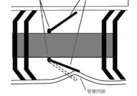
(3) Leakage at the bend deformation point limits further pressure buildup: When the magnetic flux leakage (MFL) inspection tool becomes stalled or stuck at a deformed bend section, leakage may occur, preventing further increase in the driving pressure differential. The cross-sectional view of the MFL inspection tool (MFLZ) at the bend deformation location is shown in Figure 8. When the MFLZ passes through this deformed section, the increased resistance may cause the tool to become stuck at the deformation point. At the same time, due to the ovalization of the bend, the MFLZ cups cannot fully contact the pipe wall along the major axis of the ellipse to form an effective sealing structure, resulting in significant natural gas leakage at this location and making it impossible to establish a sufficient pressure differential upstream and downstream of the MFLZ. The instantaneous gas transmission rate in the pipeline also plays a decisive role in establishing the driving pressure differential.
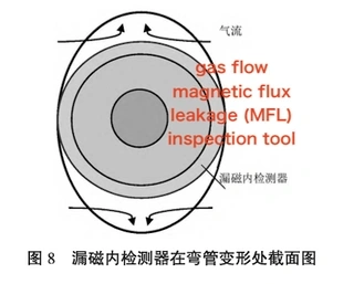
Figure 8 Cross-sectional view of the MFLZ at the bend deformation point
4. On-site excavation verification and handling
Based on the analysis in the previous section, it is likely that the MFLZ will become stuck when passing through the three aforementioned bend sections with ovalization. Therefore, it was decided to excavate the three deformation locations for verification. The on-site condition of the bends after excavation is shown in Figures 9, 10, and 11. The deformations at the three bend sections were measured, and the detailed results are presented in Table 2.
Table 2 Measurement Data for Bends
|
Serial No. |
Location (m) |
Maximum Outer Diameter (mm) |
Minimum Outer Diameter (mm) |
Calculated Ellipticity (%OD) |
|
1 |
16719 |
760 |
615 |
20.4 |
|
2 |
30468 |
716 |
655 |
8.6 |
|
3 |
32286 |
753 |
626 |
17.8 |
The excavation measurement data from the three locations in Table 2 are generally consistent with the inspection results, thereby confirming the accuracy of the detection data and the validity of the evaluation judgment. After the operator unit carried out pipe replacement and repair, the MFL inspection tool was successfully launched, effectively preventing any tool jamming during the inspection process.
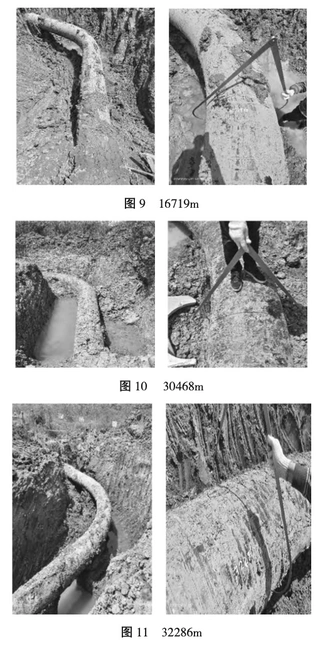
Figure 9 16719m
Figure 10 30468m
Figure 11 32286m
5. Conclusion
This study analyzes the impact of bend ovalization on the performance of the magnetic flux leakage (MFLF) inspection tool by comparing characteristic signals and deformation signals from geometric inspection data, and by integrating the structural characteristics of the MFLF tool with pipeline operating conditions. Bend ovalization is typically caused by excessive assembly forces during pipeline construction or by changes in geological conditions along the pipeline route. This phenomenon is relatively common, particularly in complex mountainous terrain. Bend ovalization represents a significant potential risk factor for MFLF tool blockage during in-line inspection and therefore requires careful attention. However, since the signal characteristics of bend ovalization are superimposed on the normal bend response, the resulting deformation features typically present as smooth transitions and can be easily overlooked during data interpretation, necessitating careful and detailed analysis for accurate identification. This places higher requirements on the rigor, technical competence, and sense of responsibility of both data analysts and field technicians.It should also be noted that if the caliper plate shows no obvious damage after passage of the pipeline cleaning tool, this does not necessarily indicate that the pipeline’s passability is unaffected. In such cases, there remains a risk of the magnetic flux leakage inspection tool becoming stuck during operation. It is recommended to carry out the in-line inspection in a step-by-step manner, closely monitor geometric deformation throughout the process, and conduct careful data analysis. This approach helps to fully eliminate the risk of MFL tool blockage caused by pipeline deformation, thereby ensuring the safe and efficient execution of the inspection operation.
Send your message to this supplier
Related Articles from the Supplier
How to Choose Heat-preservation Pipe Fittings
- Jul 27, 2016
How to choose graphite composite gaskets?
- Aug 10, 2018
How to Use Stainless Steel Press fittings?
- Feb 03, 2021

Related Articles from China Manufacturers
How to dredge spiral steel pipe
- Nov 24, 2023
How to choose spiral pipe or seamless pipe?
- Sep 01, 2023
How to Choose the Right Pipe End for Your System
- May 21, 2026
How to Solve Bubble Problem of Precision Light Pipe
- Aug 25, 2023
How to Solve Bubble Problem of Precision Light Pipe
- Aug 14, 2023
How to Detect the Quality of Spiral Steel Pipe
- Jul 11, 2023

How to improve the quality of steel pipe welding
- May 22, 2024
Related Products Mentioned in the Article
Supplier Website
Source: https://www.landeepipefitting.com/how-pipe-deformation-affects-magnetic-flux-leakage-mfl-detection-case-study-analysis.html