Analysis of Loading-Port Flange Leakage in a Reactor Coolant Purification Resin Bed of a Power Plant
Abstract
This study investigates leakage at the loading-port flange of a mixed-resin bed in a power-plant reactor coolant purification system. The bolt tightening torque was verified, and the tightening procedure, flange geometric parameters, and gasket strength test data for both new and previous batches were analyzed. Finite-element analysis (FEA) of the flange sealing structure was conducted using ANSYS Workbench. The results indicate that the primary cause of the leakage was incomplete gas venting at the loading port.
Because flange sealing requirements are more stringent for gaseous media than for liquids, the safety margin for gas sealing is inherently lower. By increasing the height of the raised face on the flange top-cover sealing surface, the contact pressure at the lower portion of the inner sealing ring is increased under the same bolt preload. Consequently, when sealing gaseous media, the number of effective sealing lines at the lower portion of the inner ring increases from one to three. This enhances the gas-sealing reliability of the mixed-resin-bed loading-port flange and effectively addresses the observed leakage issue. The analysis also revealed that the maximum contact stress between the inner sealing ring and the top cover exceeds the yield strength of the top-cover sealing-surface material. Therefore, from a long-term operational perspective, it is necessary to monitor the contact interface between the nickel gasket and the sealing surface to prevent progressive deformation from compromising flange sealing performance.
Introduction
The reactor coolant purification system of a nuclear power plant (hereinafter referred to as the KBE system) comprises three resin beds—cation, anion, and mixed—primarily used to purify the primary-loop coolant. To maintain the purification capacity of the system during plant operation, resin is replenished through the resin-bed loading port during each major overhaul. During a recent outage, following replacement of the mixed-bed resin and installation of a new flange gasket at the loading port, the flange was reassembled and sealed. When the resin bed was subsequently pressurized to 15.7 MPa, the pressure transmitter positioned between the two sealing rings at the loading port recorded a gradual increase from 0.02 MPa to 0.06 MPa over 7 hours, with a continuing upward trend, indicating the presence of leakage. The resin bed of the KBE system also forms part of the pressure boundary; therefore, its sealing integrity directly influences the safe and reliable operation of the plant. Flange sealing performance is affected by multiple factors, including service conditions, sealing-surface characteristics, the mechanical properties of the flange and bolts, gasket quality and performance, and the magnitude and sequence of bolt preload. Statistical data from the UK Offshore Operators Association (UKOOA) indicate that 81% of flange seal failures are caused by improper bolt loading. To identify the root cause of leakage at the mixed-resin bed loading-port flange of the KBE system, the following analyses were conducted.
1. Equipment Structure
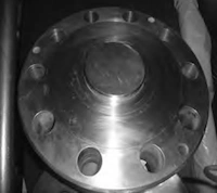
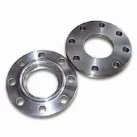
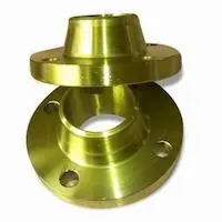
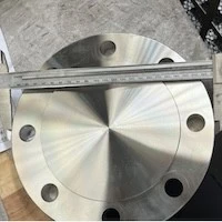
Both the manhole and the loading port of the mixed-resin bed employ a double-ring sealing configuration, with nickel gaskets serving as the sealing elements. The sealing groove features a trapezoidal cross-section. M36 double-ended studs (material: 38KhN3M, grade DA) are used at the loading port to apply preload to the gasket. The structural dimensions of the resin-bed loading port are shown in Figures 1–4.
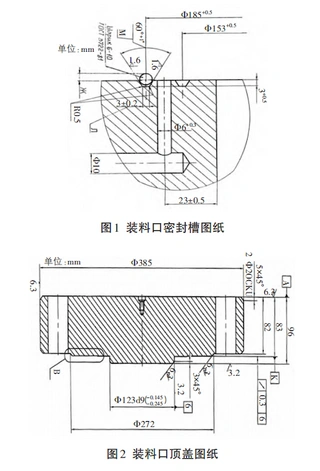
Figure 1. Geometry of the loading-port sealing groove
Figure 2. Loading-port top cover
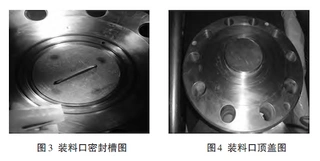
Figure 3. Geometry of the loading-port sealing groove
Figure 4. Loading-port top cover
2. Tightening Torque Calculation
To verify the adequacy of the tightening torque applied to the loading-port flange bolts, the required bolt preload was recalculated as follows.
(1) Required Bolt Preload for Gasket Seating
During gasket pre-compression, the total required bolt preload is
Where:
Dm— mean gasket diameter, 169 mm
n — number of gaskets, 2
b0 — nominal gasket width, 6 mm
b — effective gasket width, b=0.6xb0
Rp0.2— gasket yield strength, 165 MPa
q0 — required gasket seating stress
(2) Minimum Gasket Load under Design Pressure
Under the design pressure, the minimum load acting on the flange gasket is:
![]()
Where:
m — gasket factor, 2.5
P — design pressure, 17.6 MPa
X — gasket strength coefficient under operating conditions, 1.0
(3) Minimum flange separating force under design pressure
![]()
(4) Minimum gasket load under hydrostatic test pressure
![]()
where
Ph — hydrostatic test pressure, 24.5 MPa.
(5) Minimum flange separating force under hydrostatic test pressure
![]()
(6) Final required total bolt preload
![]()
(7) Tightening torque per bolt
The tightening torque for a single bolt is calculated as
![]()
Where:
K — tightening torque coefficient, determined by the bolt surface condition and the presence or absence of lubrication, taken as 0.1–0.3.
d — nominal bolt diameter, 36 mm.
N — number of bolts, 10.
Tightening Procedure
Based on the above calculations, a tightening torque of 1800 N·m was specified for the loading-port bolts, which meets the sealing requirements. The bolts are tightened using a hydraulic wrench in three passes following a criss-cross sequence. Final tightening is performed to 1800 N·m, with an additional 1.5-turn rotation to ensure that the preload of each bolt meets the specified requirement.
3. Bolt Strength
The loading-port bolts are made of 38KhN3MDA steel. The material properties for both the loading-port and manhole bolts are as follows: yield strength at 20 °C, 784 MPa; ultimate tensile strength at 20 °C, 882 MPa; and allowable stress, 373 MPa.
The loading port employs M36 bolts. Under a tightening torque of 1800 N·m, the resulting stress in each bolt is
![]()
Where:
MM36 — tightening torque of the loading-port bolt, 1800 N·m
d — nominal bolt diameter, 36 mm
K — torque coefficient, 0.2
The calculated bolt stress is below both the yield strength and the allowable stress of the bolt material. Therefore, the strength of the loading-port and manhole bolts meets the design requirements.
4. Data Analysis
4.1 Standard Geometry Analysis
According to the design drawings of the KBE system mixed-resin bed, the seating condition of a 6 mm-diameter nickel gasket in the standard sealing groove is shown in Figure 5.
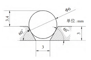
Figure 5. Seating of the standard nickel gasket in the sealing groove
Based on the dimensional tolerances specified in the resin-bed drawings, the maximum and minimum protrusion heights of the nickel gasket above the sealing groove were assessed. When the included angle of the trapezoidal sealing groove is 60°, the groove bottom width is 2.8 mm and the groove depth is 3.0 mm. Under these conditions, the nickel gasket exhibits its maximum protrusion height above the groove (Figure 6a). When the included angle is 61°, the groove bottom width is 3.2 mm and the groove depth is 3.5 mm. Under these conditions, the nickel gasket exhibits its minimum protrusion height above the groove (Figure 6b).
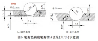
(a) Maximum protrusion (b) Minimum protrusion
Figure 6. Maximum and minimum protrusion of the gasket above the sealing groove
As shown in Figure 6, the protrusion height of the gasket above the sealing groove ranges from 2.69 to 3.58 mm (corresponding groove depth: 2.42–3.31 mm). The clearance between the nickel gasket and the groove bottom ranges from 0.19 to 0.58 mm.
4.2 Actual Data Analysis of the Loading-Port Flange
In this study, a 6 mm-diameter steel ball was used to simulate the seating of the nickel gasket in the sealing groove, and the groove depth was measured accordingly. Ten measurement points were taken in situ on the loading-port sealing groove, and the results are presented in Table 1.
Table 1. Depth corresponding to seating of a 6-mm steel ball in the loading-port sealing groove (mm)
|
Point |
Outer ring |
Inner ring |
Point |
Outer ring |
Inner ring |
|
1 |
2.64 |
3.14 |
6 |
2.60 |
3.10 |
|
2 |
2.57 |
3.14 |
7 |
2.62 |
3.12 |
|
3 |
2.57 |
3.13 |
8 |
2.67 |
3.15 |
|
4 |
2.59 |
3.10 |
9 |
2.63 |
3.16 |
|
5 |
2.59 |
3.09 |
10 |
2.65 |
3.17 |
As shown in Table 1, the measured groove depths for both the inner and outer nickel rings fall within the design range of 2.42–3.31 mm. The following analysis examines the contact sequence between the loading-port top cover of the mixed-resin bed and the inner and outer sealing rings. The calculated protrusion heights of the nickel gasket above the sealing groove are presented in Table 2. As shown, the outer ring (mean 3.39 mm) protrudes on average 0.52 mm more than the inner ring (mean 2.87 mm). The design height of the top-cover boss is 0.40 ± 0.20 mm (Figure 7). The actual measured boss height is 0.55 mm, and no noticeable indentation was observed on the top-cover sealing surface. Consequently, after the inner ring makes contact with the top cover, the remaining gap between the top cover and the outer ring is approximately 0.03 mm. This indicates that during tightening and sealing, the inner ring engages the top cover before the outer ring.
Table 2. Protrusion height A of the nickel gasket above the loading-port sealing groove (mm)
|
Point |
Outer ring |
Inner ring |
Point |
Outer ring |
Inner ring |
|
1 |
3.36 |
2.86 |
6 |
3.40 |
2.90 |
|
2 |
3.43 |
2.86 |
7 |
3.38 |
2.88 |
|
3 |
3.43 |
2.87 |
8 |
3.33 |
2.85 |
|
4 |
3.41 |
2.90 |
9 |
3.37 |
2.84 |
|
5 |
3.41 |
2.91 |
10 |
3.35 |
2.83 |
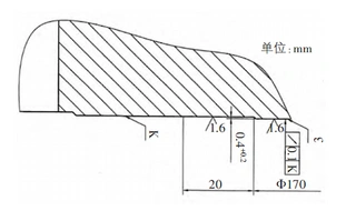
Figure 7. Boss height of the loading-port top cover
4.3 Finite Element Analysis of the Loading-Port Flange
4.3.1 Model Establishment
Based on in situ measurements of the 2KBE50AT001 mixed-resin-bed loading-port flange, the dimensions of the inner and outer sealing grooves are illustrated in Figure 8.
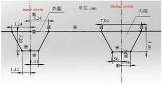
Figure 8. Dimensions of the inner and outer sealing grooves
Finite-element analysis (FEA) of the flange assembly was conducted using ANSYS Workbench 19.0. The bolted flange connection is centrally symmetric, and the circumferential load distribution exhibits periodic symmetry. Considering this symmetry, only half of the flange assembly was modeled for analysis. This approach meets the analysis objectives while reducing model size and computational effort.
The attached pipe length in the flange model was taken as:
L=2.5Rt
Here, R denotes the mean pipe radius, and ttt denotes the pipe wall thickness. The resulting half-flange model is illustrated in Figure 9. Since this study focuses on the contact pressure acting on the sealing gaskets, the bolt geometry was simplified, as shown in Figure 10. Bolt tightening was simulated by applying bolt preload, and the models of the inner and outer nickel gaskets are presented in Figure 11.
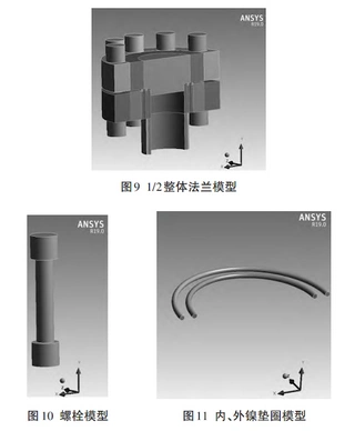
Figure 9. Half-model of the integral flange
Figure 10. Simplified bolt model
Figure 11. Inner and outer nickel gasket models
4.3.2 Mesh Generation
The finite-element meshes of the complete flange assembly, the bolts, and the nickel gaskets are presented in Figures 12–14.
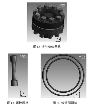
Figure 12. Mesh of the overall flange assembly
Figure 13. Bolt mesh
Figure 14. Nickel gasket mesh
4.3.3 Material Properties
Since new nickel gaskets were installed during this overhaul, strength tests were conducted on both the new-batch and previous-batch gaskets used on site, using a dedicated strength-testing rig (Figure 15). The corresponding stress–strain curves are presented in Figure 16. For the new-batch nickel gasket, the yield strength Rp0.2 is 160 MPa, the elastic modulus is 6.8×10⁹ Pa, and the ultimate strength is 314 MPa. For the new-batch nickel gasket, the yield strength Rp0.2 is 160 MPa, the elastic modulus is 6.8+9 Pa, and the ultimate tensile strength is 314 MPa. For the previous-batch nickel gasket, the yield strength Rp0.2 is 165 MPa, the elastic modulus is 8e+9 Pa, and the ultimate tensile strength is 324 MPa.
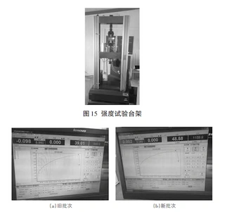
Figure 15. Nickel-gasket strength test rig
Figure 16. Stress–strain curves of previous-batch and new-batch nickel gaskets
After compilation, the material properties employed in the full FEA model are summarized in Table 3.
Table 3. Material properties of model components
|
Component |
Material |
Elastic modulus (Pa) |
Poisson’s ratio |
Yield strength (MPa) |
|
Top cover |
08Kh18N10T |
2.0×10¹¹ |
0.30 |
216 |
|
Flange |
08Kh18N10T |
2.0×10¹¹ |
0.30 |
216 |
|
Bolt |
38KhN3MDA |
2.06×10¹¹ |
0.30 |
784 |
|
Nickel gasket |
HNII-2 |
6.8×10⁹ / 8.0×10⁹ |
0.44 |
160 / 165 |
4.3.4 Constraints and Boundary Conditions
The simulation procedure was performed in three sequential load steps:
In the first step, a bolt preload of 250 kN was applied to each of the five modeled bolts, which were then locked. In the second step, an internal pressure of 15.7 MPa was applied to the inner surface of the flange assembly. In the third step, the analysis was performed with weak springs and large-deformation effects enabled to ensure numerical stability and convergence.
4.3.5 Post-Processing and Sealing Assessment
According to Russian standard TIHA3T-7-002-86-E, flange sealing performance is evaluated based on the contact pressure acting on the gasket. The standard specifies that a reliable seal is achieved only when the gasket contact pressure exceeds the required sealing stress:
q0=ϕRp0.2Alternatively, under operating pressure:
q≥mPqwhere:
m — gasket factor
P — operating pressure (15.7 MPa)
Rp0.2 — gasket yield strength
ϕ — sealing coefficient (2.4 for liquid media, 3.0 for gaseous media)
Therefore, effective sealing of the KBE mixed-resin-bed loading-port flange requires that both contact interfaces of the inner nickel gasket—the upper contact with the top cover and the lower contact with the flange groove—exceed the maximum required sealing pressure, forming a continuous annular sealing line. Because the KBE resin bed must be vented during filling and pressurization, and the vent nozzle is located approximately 50 mm below the flange plane, some gas may remain trapped at the top of the vessel. Consequently, the sealing condition should be evaluated for gaseous service. During the overhaul, new-batch nickel gaskets were installed; therefore, Rp0.2=160 MPa was adopted. For gaseous sealing, m=4.5m and ϕ=3.0, resulting in a required gasket contact pressure of
qgas=3Rp0.2=480 MPa
Under the specified tightening torque of 1800 N·m, the equivalent bolt preload is approximately 250 kN. The resulting gasket contact-pressure distribution, obtained from FEA, is shown in Figures 17 and 18. Regions with contact pressures ≥ 480 MPa (dark areas) indicate sealing lines for gaseous media, whereas regions ≥ 384 MPa (light areas) indicate sealing lines for liquid media. White regions indicate areas where the contact pressure is below the minimum required for sealing.
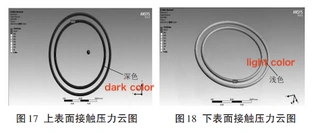
Figure 17. Contact-pressure contour of the inner gasket upper surface
Figure 18. Contact-pressure contour of the inner gasket lower surface
As shown in Figures 17 and 18, the upper contact surface of the inner gasket forms a continuous annular sealing line under both gaseous and liquid conditions. In addition to a broad high-pressure band at the top, three lower-pressure sealing bands appear on the lower surface. This indicates that, in the absence of trapped gas, three effective sealing lines are formed at the lower interface, ensuring reliable sealing for liquid media. However, at the lower contact interface under gaseous conditions, only a single high-pressure sealing band approximately 0.8 mm wide is observed. This indicates that when gas remains trapped at the top of the resin bed, only one effective sealing line is formed at the lower interface, resulting in a reduced sealing safety margin. FEA results for the previous-batch nickel gaskets (Figures 19 and 20) exhibit essentially the same contact-pressure distribution pattern as observed for the new-batch gaskets.
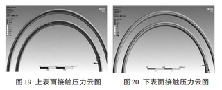
Figure 19. Upper-surface contact-pressure contour (previous batch)
Figure 20. Lower-surface contact-pressure contour (previous batch)
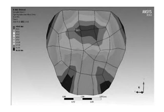
Figure 21. Equivalent-stress contour of the nickel gasket
The maximum equivalent stress in the new-batch gasket reaches 449.61 MPa, exceeding the ultimate strength of the nickel material (314 MPa), indicating the potential for localized damage. Therefore, penetrant testing (PT) was conducted on the removed gaskets. The results (Figure 22) revealed no evidence of cracks or other damage.
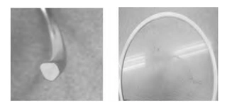
Figure 22. Penetrant-testing results of removed nickel gasket
Summary of FEA Findings
Finite-element analysis indicates that, under the specified tightening torque of 1800 N·m, the presence of residual gas at the top of the KBE mixed-resin bed increases the sealing pressure required compared with liquid-service conditions. As a result, the gas-sealing safety margin of the loading-port flange is low, rendering the sealing performance highly sensitive to bolt preload, sealing-surface machining accuracy, and minor deformations occurring during long-term operation. These factors may result in loss of sealing at the inner ring of the resin-bed loading port.
5. Improvements
5.1 Improvement Scheme
According to the original design concept, the inner sealing ring is intended to contact the top-cover sealing surface before the outer ring. Accordingly, the top-cover boss was optimized by increasing its height from 0.55 mm to 0.75 mm. An alternative approach is to extend the venting duration of the mixed-resin bed to ensure complete discharge of gas above the loading port, thereby enhancing sealing reliability. However, since the vent nozzle is located approximately 50 mm above the loading port, complete gas evacuation cannot be guaranteed.
5.2 Finite Element Analysis of the Improved Flange
A revised finite-element model was constructed incorporating the optimized boss height and a new batch of nickel gaskets. Finite-element analysis was conducted under otherwise identical conditions—including mesh density, contact definitions, bolt preload, and internal pressure—and the resulting gasket contact-pressure contours are shown in Figures 23 and 24.
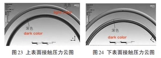
Figure 23. Contact-pressure contour of the inner gasket upper surface (optimized)
Figure 24. Contact-pressure contour of the inner gasket lower surface (optimized)
After optimizing the sealing surface, three continuous high-pressure sealing lines formed on the lower surface of the inner ring, indicating a marked improvement in sealing safety and effectiveness. To evaluate sealing performance under hydrostatic test conditions, the internal pressure was raised to 24.5 MPa, while all other parameters remained unchanged. The resulting gasket contact-pressure contours are shown in Figures 25 and 26.
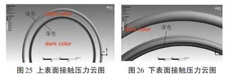
Figure 25. Upper-surface contact-pressure contour at 24.5 MPa
Figure 26. Lower-surface contact-pressure contour at 24.5 MPa
The optimized geometry once again generated three continuous high-pressure sealing lines at the lower interface of the inner ring, confirming a marked improvement in sealing safety. Overall, the optimized flange design guarantees reliable sealing under both the operating pressure of 15.7 MPa and the hydrostatic test pressure of 24.5 MPa.
5.3 Improvement Effect
After optimizing the KBE resin-bed loading-port flange and installing a new batch of nickel gaskets, both sealing rings successfully passed a 2.8 MPa leak-tightness test. When the system pressure was subsequently increased to 15.7 MPa, no pressure rise was detected in the loading-port flange leakage-monitoring line, confirming that the leakage had been eliminated.
6. Conclusions
This study investigated the root cause of leakage at the mixed-resin-bed loading-port flange and implemented effective structural optimizations, successfully resolving the on-site leakage issue. However, finite-element analysis of the loading-port flange indicates that the maximum contact stress between the inner sealing ring and the top cover reaches approximately 304 MPa, exceeding the yield strength of 08Kh18N10T (≈185 MPa). From a long-term operational perspective, this stress level could cause localized plastic deformation at the flange contact interface. Therefore, during long-term operation, the contact area between the nickel gasket and the sealing surface should be periodically inspected to detect potential deformation and prevent its progression, which could compromise the flange’s sealing performance.
Send your message to this supplier
Related Articles from the Supplier
Analysis of Leakages of Steam Flange Sealing
- Jun 15, 2023


Analysis of the Cracking Cause of High-Neck Flanges
- Oct 28, 2024


Related Articles from China Manufacturers

Analysis of Export of China’s Bags
- Mar 07, 2016

Analysis of China's Imported Bags
- Mar 07, 2016

Analysis of Welded Elbow Materials
- Aug 20, 2015


Analysis of Chinese Sanitary Napkin Industry
- May 10, 2016
-320x320.webp)
Analysis of China Automatic Packaging Machine Status
- Jul 20, 2016
Related Products Mentioned in the Article
Supplier Website
Source: https://www.landeeflange.com/analysis-of-loading-port-flange-leakage-in-a-reactor-coolant-purification-resin-bed-of-a-power-plant.html