Why Extended Bonnet Designs Used in Cryogenic Valves
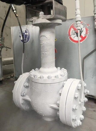
In the pipelines used for transporting cryogenic media such as liquefied natural gas (LNG), liquid oxygen, and liquid nitrogen, a distinctive type of valve structure can be seen almost everywhere, a valve with a noticeably taller bonnet than ordinary industrial valves. If you have ever closely observed cryogenic valves in an LNG receiving terminal or an air separation unit, you may have noticed that their bonnets are unusually long, resembling a slender neck connecting the valve body to the operating mechanism or actuator.
This seemingly simple elongation is far from a cosmetic choice or a mere installation convenience. On the contrary, it represents one of the most critical safety technologies in cryogenic valve engineering. The extended bonnet is often referred to as the lifeline of a cryogenic valve, and for good reason. But why is this long-neck design so essential? How does it resolve the challenges of sealing integrity, operational safety, and reliability under extreme cryogenic conditions?
This article explores the technical rationale behind extended bonnet designs and explains why they are indispensable in LNG and other ultra-low-temperature applications.
Extended Bonnet: A Defining Feature of Cryogenic Valves
Cryogenic valves, typically designed for operating temperatures ranging from –40 °C down to –196 °C, differ from conventional valves in many ways. The most immediately visible distinction is the extended bonnet structure. Whether the valve is a gate valve, globe valve, ball valve, or butterfly valve, relevant standards clearly require an appropriately designed extended bonnet based on the intended service temperature.
This long neck is not an aesthetic feature, nor is it simply meant to ease installation. Instead, it performs several vital functions that directly affect the safety and performance of cryogenic systems.
At its core, the extended bonnet serves to elevate the operating mechanism and the packing system away from the cryogenic zone. Imagine a valve mounted directly on a pipeline carrying LNG at –162 °C without an extended bonnet. Operators would have to touch or operate components that are dangerously cold, posing a severe frostbite hazard. More critically, the valve packing would be exposed to extreme temperatures, leading to loss of elasticity, seal failure, and potentially catastrophic leakage.
Thus, the extended bonnet is fundamentally a protective and functional design, ensuring both human safety and sealing reliability.
Three Core Functions of the Extended Bonnet Design
At first glance, simply making the bonnet longer may seem like a straightforward solution. However, from an engineering perspective, this design cleverly applies the principles of heat transfer to create a stable and controlled temperature gradient.
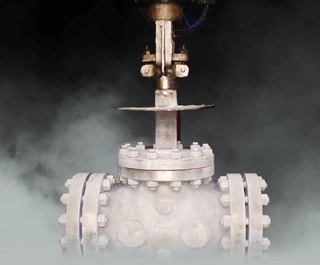
By significantly increasing the heat conduction path, the extended bonnet establishes a “thermal staircase” from bottom to top. The lower end of the bonnet is exposed to cryogenic temperatures as low as –160 °C or even –196 °C, while the upper section gradually warms due to thermal resistance and heat exchange with the ambient environment. As a result, the packing chamber at the top of the bonnet can maintain a temperature above 0 °C.
This controlled temperature distribution allows operational safety and sealing performance, two normally conflicting requirements under cryogenic conditions, to coexist. Specifically, the extended bonnet fulfills the following three essential functions.
1. Keeping Manual Operations Away from Extreme Cold
In cryogenic service, the valve body temperature may fall to –100 °C or lower. The extended bonnet increases the distance between the cryogenic zone and the operating handwheel or actuator. This elevation ensures that operators handle components that remain close to ambient temperature.
By physically separating human interaction points from the ultra-low-temperature zone, the risk of cold burns and frostbite is eliminated. International standards such as BS 6364 specify minimum extension lengths, typically no less than 250 mm for non-cold-box applications, to ensure a sufficient safety margin for manual operation.
2. Protecting Valve Packing
The sealing performance of the packing system is critical to cryogenic valve reliability. As temperature decreases, conventional packing materials lose elasticity, significantly reducing their sealing capability. Once leakage begins, escaping cryogenic fluid can freeze at the interface between the valve stem and packing.
This ice formation not only impedes valve operation but also causes severe mechanical damage. During stem movement, frozen media can abrade the packing like a cutting tool, eventually leading to major leakage or complete seal failure.
The extended bonnet prevents this scenario by ensuring that the packing chamber remains above 0 °C, ideally above 8 °C. Within this temperature range, impregnated asbestos-PTFE packing or other cryogenic-grade materials retain sufficient elasticity and sealing performance.
In effect, the extended bonnet functions like a “thermal elevator,” lifting the packing system out of the cryogenic basement and placing it in a stable, thermally safe zone where it can perform reliably.
3. Minimizing Cryogenic Energy Loss
Cryogenic pipelines are typically covered with thick insulation layers to prevent heat ingress and reduce cryogenic energy loss. The extended bonnet allows the valve stem and packing gland to pass cleanly through the insulation, positioning the packing gland entirely outside the insulated zone.
This design offers two major advantages. First, it simplifies insulation installation and reduces cold leakage along the bonnet. Second, it allows maintenance activities, such as tightening gland bolts or adding packing, to be performed without removing or damaging the insulation. This significantly reduces maintenance costs and minimizes cryogenic losses during servicing.
In installations equipped with cold boxes, such as air separation units, extended bonnets allow the valve bonnet to pass through the cold box wall. Internal components can be serviced by removing the bonnet while leaving the valve body welded in place, eliminating the need for hot work and improving operational safety.
Drip Plate Design
In humid environments, extended bonnets face an often-overlooked threat: condensation. The upper portion of the bonnet is exposed to ambient air while remaining relatively cold, causing moisture in the air to condense on the bonnet surface.
If condensation water flows downward, it may drip onto the body-bonnet flange bolts, leading to corrosion over time and compromising maintenance safety. If it drips onto insulation, it can degrade insulation performance and accelerate corrosion under insulation (CUI).
To mitigate this issue, engineers incorporate drip plates into extended bonnet designs. These plates, with diameters larger than the body-bonnet flange, act like miniature umbrellas. They divert condensed water away from bolts and insulation, allowing droplets to fall safely from the perimeter.
Positioned outside the insulation layer, drip plates effectively protect fasteners, insulation, and the upper valve structure. Studies have shown that valves equipped with drip plates exhibit more favorable temperature gradients and significantly reduced condensation-related issues.
Extended Bonnet Length Requirements
The length of an extended bonnet is not arbitrary; it is determined by strict international standards. Three major references are commonly used:
- BS 6364: Specifies extension dimensions for DN15–DN500 valves. For non-cold-box applications, a minimum extension length of 250 mm is required.
- MSS SP-134: Covers DN15–DN300 valves. Non-cold-box extensions are generally longer than those specified in BS 6364, while cold-box extensions are shorter.
- Shell MESC SPE 77/200: Provides the most detailed guidance, covering DN15–DN1200 valves across multiple temperature ranges.
In practical engineering, if the insulation thickness exceeds the standard extension length, the bonnet must be further extended to ensure proper packing placement. For critical cryogenic services, SPE 77/200 is often preferred due to its comprehensive coverage and detailed classification.
Essential Safety Features of Low-temperature Valves
- Automatic Cavity Pressure Relief: In cryogenic valves handling LNG or similar media, a unique risk arises when the valve is closed. Cryogenic liquid trapped in the valve cavity absorbs heat and vaporizes, potentially expanding in volume by more than 600 times. This rapid expansion can cause dangerous pressure buildup, leading to seal failure or even rupture. To address this risk, cryogenic valves must incorporate automatic cavity pressure relief designs that release excess pressure when it exceeds safe limits. The specific relief mechanism varies depending on valve type, gate valves and ball valves require different approaches due to their distinct sealing principles.
- Anti-Static Design: Cryogenic media are often flammable, and static electricity generated by fluid flow can pose a serious ignition risk. Cryogenic valves incorporate conductive paths between the valve stem and body, allowing static charges to dissipate safely, much like a lightning rod. This anti-static design is a critical safety measure in LNG and other hazardous cryogenic services.
- Fire-Safe Design: In the event of a fire, valves must withstand rapid temperature changes without losing structural integrity or sealing capability. Valve bodies must accommodate thermal expansion and contraction, and seat designs must remain functional under fire exposure. Gate valves may use flexible or split wedges, while globe valves often employ plug-type discs. These designs help maintain sealing reliability even during extreme thermal shock.
Materials and Sealing Characteristics for Cryogenic Service
- Valve Stem Treatment: Valve stems are typically chrome-plated, nickel-phosphorus plated, or nitrided to increase surface hardness and corrosion resistance. These treatments also prevent galling between the stem, packing, and gland components—a common issue at low temperatures.
- Gasket Selection: Gaskets must exhibit excellent low-temperature resilience, preload retention, and minimal stress relaxation. Ordinary gaskets become brittle at cryogenic temperatures and are unsuitable. Specialized cryogenic gaskets are therefore mandatory.
- Packing Arrangement: Cryogenic valves often use a two-stage packing system with a metallic spacer ring between packing sets. In the event of leakage, lubricant can be injected into the spacer to form an auxiliary seal. Some designs employ self-energizing double packing systems, where internal pressure enhances sealing effectiveness. In all cases, the packing chamber is positioned at the top of the extended bonnet, away from the cryogenic zone.
- Sealing Surfaces and Closure Elements: Critical sealing surfaces, such as discs, seats, and balls, are typically hardfaced with cobalt-chromium-tungsten alloys. These surfaces are precisely machined and lapped to ensure wear resistance and sealing integrity at low temperatures. For soft-seated designs, standard PTFE is only suitable down to approximately –70 °C. LNG applications at –162 °C require modified materials such as PCTFE.
- Bolting Design: Flange bolts in cryogenic service are subject to repeated thermal cycling, which can cause fatigue failure at thread roots. To mitigate this risk, fully threaded bolts are used to eliminate stress concentration points and improve fatigue resistance.
Conclusion
The extended bonnet may appear to be a simple structural feature, but in reality, it represents the culmination of cryogenic valve engineering. It is not merely an elongation; it is a carefully integrated design combining thermodynamics, materials science, sealing technology, and safety engineering. From protecting operators against frostbite to preserving sealing integrity, from simplifying maintenance to safeguarding system safety, every detail of the extended bonnet contributes to the reliable operation of cryogenic systems. As the global energy transition continues, demand for LNG and other cryogenic applications is steadily increasing. Understanding the critical technologies embedded in something as seemingly ordinary as a valve bonnet not only enables better engineering decisions but also deepens our appreciation for modern industrial safety design. It is these unassuming long necks that quietly stand guard, forming a vital line of defense in the extreme cold environments of the LNG industry.
Send your message to this supplier
Related Articles from the Supplier
Why Extended Bonnet Designs Used in Cryogenic Valves
- Jan 28, 2026
Guide to Choosing Inconel Valves: Why and How
- Apr 11, 2026
Related Articles from China Manufacturers
Why use extended bonnet for cryogenic valves?
- Nov 10, 2018

Why the Control Valve Is Called Full-featured Valve
- May 13, 2015
Why should pipes and valves be insulated?
- Apr 20, 2019
Why Should Soft Sealing Valves Be Anti-static?
- Feb 10, 2022

Related Products Mentioned in the Article
Zhejiang Kosen Valve Co., Ltd.
- https://www.kosenvalve.com/
- Business Type: Industry & Trading, Manufacturer,
Supplier Website
Source: https://www.kosenvalve.com/media-hub/why-extended-bonnet-designs-used-in-cryogenic-valves.html