L-Type vs. T-Type 3-Way Ball Valves: How to Choose
In industrial pipeline systems, the diversion, mixing, and flow direction switching of fluids are common control requirements. As a valve device with a compact structure and diverse functions, the 3-way ball valve can achieve complex fluid control functions within a single valve body. This article will focus on the two main types of 3-way ball valves, L-type and T-type, and provide a comprehensive analysis from structural principles, functional characteristics, application scenarios to selection key points, helping you make the correct choice according to actual needs.
Structure and Principle of 3-Way Ball Valve
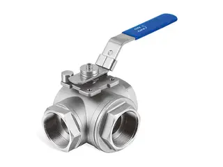
A 3-way ball valve is a rotary valve with three channel ports. Compared with the common 2-way ball valve, it has one more connection port. Inside the valve body is a ball with a through hole, and by rotating 90 degrees (a quarter turn), the connection method of the fluid channels is changed, thereby achieving precise control of the fluid flow direction. The three ports of a 3-way ball valve are usually marked as A, B, and C, among which the middle channel is often used as the common port. According to the different shapes of the through hole inside the ball, 3-way ball valves are mainly divided into two structures: L-type and T-type.
The main components of a 3-way ball valve include:
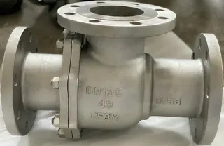
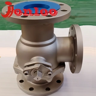
- Ports: Three threaded or flanged connection ports used to connect the pipeline system.
- Ball: A spherical structure with an L-type or T-type through hole, which is the core component for controlling fluid direction.
- Seats: Usually made of PTFE (polytetrafluoroethylene) or similar materials, used to support the ball and achieve sealing shutoff.
- Stem & Seals: Connect the ball with the actuator or handle while preventing medium leakage.
- Actuator/Handle: Can be a manually operated handle or an electric or pneumatic actuator, used to drive the rotation of the ball.
The 3-way ball valve belongs to a quarter-turn operated valve. When the handle or actuator drives the ball to rotate, the relative position between the through hole on the ball and the valve body channels changes, thereby changing the connection relationship of the fluid. The fluid flows through the through hole on the ball, and different rotation positions correspond to different channel connection states.
Detailed Explanation of L-Type 3-Way Ball Valve
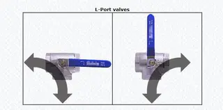
The ball inside the L-type 3-way ball valve is machined into an L-shaped through hole, forming a 90-degree right-angle turning structure. This design allows the ball to connect only two of the three channels at any time, while the third channel is always in a closed state.
1. Working Mode of L-Type 3-Way Ball Valve
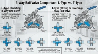
Taking the middle channel as the common port as an example, the typical working states of the L-type ball valve are as follows:
At the 0-degree position, the fluid enters from the bottom channel (common port) and flows out from the left channel, while the right channel is completely closed. When the valve rotates 90 degrees, the fluid enters from the bottom channel and flows out from the right channel, while the left channel is closed. Some designs allow a transitional position, at which time the middle channel may be partially connected to both side channels simultaneously, but most actuators limit it to two clear positions to ensure control accuracy.
2. Functional Characteristics of L-Type 3-Way Ball Valve
The core function of the L-type 3-way ball valve is diversion and switching, with the following characteristics:
It can only switch the flow direction between two outlets and cannot connect all three channels at the same time. It can achieve complete shutoff of the fluid when the ball rotates to a position where the through hole does not align with any channel. The structure is relatively simple and the cost is low. The operation is clear and easy to control.
3. Typical Application Scenarios of L-Type 3-Way Ball Valve
The L-type 3-way ball valve is suitable for situations where fluid needs to be delivered to different locations at different times:
- Tank switching: A pump supplies liquid alternately to two storage tanks, and the feeding control of different tanks is realized by rotating the valve.
- Pipeline switching: Switch fluid between different process flows or pipelines to achieve flexible adjustment of the production line.
- Bypass control: Realize bypass flow during equipment maintenance to ensure continuous system operation.
- Seasonal switching: Switch fluid paths in heating or cooling systems according to seasons, such as switching between heating in winter and cooling in summer.
- Simple distribution: Select raw material A or raw material B to enter during chemical reactor feeding, but not use both at the same time.
What is T-Type 3-Way Ball Valve?
The ball inside the T-type 3-way ball valve is machined into a “T”-shaped through hole, consisting of a straight channel and a vertical branch. This structure provides more flexible fluid control methods.
1. Working Mode of T-Type 3-Way Ball Valve
The T-type ball valve can achieve multiple flow path states:
In the mixing condition, fluid enters from the left and right channels respectively, merges, and flows out from the bottom channel. In the diverting condition, fluid enters from the bottom channel and flows out simultaneously from the left and right channels. In the straight-through condition, fluid enters from the left channel and flows directly out from the right channel without passing through the bottom channel. In the fully open state, the three channels can flow freely with each other, realizing simultaneous connection of all three ways.
2. Functional Characteristics of T-Type 3-Way Ball Valve
The core function of the T-type 3-way ball valve is mixing and distribution, with the following characteristics:
It can realize simultaneous connection of three channels. It supports multiple working conditions such as fluid mixing, diversion, and straight-through. It has flexible functions and a wide range of applications. The structure is relatively complex and the cost is high.
3. Typical Application Scenarios of T-Type 3-Way Ball Valve
The T-type 3-way ball valve is suitable for situations where fluid mixing or multi-way distribution is required:
- Temperature control: Mixing hot and cold water to adjust supply temperature, such as constant temperature control in HVAC systems.
- Simultaneous liquid supply: Supply liquid to two storage tanks at the same time to improve efficiency.
- Chemical mixing: Mix two chemicals in proportion before reaction to achieve precise ratio control.
- Fluid distribution: Distribute fluid to different process units to achieve multi-way output.
- Cleaning circuit: Switch between normal process flow and CIP (Clean-In-Place) flow to meet hygienic application requirements.
Comparison Between L-Type and T-Type 3-Way Ball Valves
The main differences between L-type and T-type 3-way ball valves are reflected in the following aspects:
- Through hole shape: L-type adopts an L-shaped 90-degree right-angle through hole, while T-type adopts a T-shaped structure with a straight channel and a vertical branch.
- Main function: L-type is mainly used for diversion and switching, while T-type is mainly used for mixing and distribution.
- Channel connection capability: L-type can only connect two channels at any time, while T-type can realize simultaneous connection of three channels.
- Fluid mixing capability: L-type does not support fluid mixing, while T-type supports mixing of two or more fluids.
- Complete shutoff capability: L-type can achieve complete shutoff, while some T-type designs may not support complete shutoff.
- Structural complexity: L-type structure is relatively simple, while T-type structure is relatively complex.
- Cost: L-type has lower cost, while T-type has higher cost.
- Operating positions: L-type usually has two effective working positions, while T-type usually has three working positions.
- Typical applications: L-type is commonly used for tank switching, pipeline switching, and bypass control, while T-type is commonly used for temperature regulation, fluid mixing, and proportional distribution.
Selection of Actuation Methods for 3-Way Ball Valves
- Manual 3-Way Ball Valve: The manual 3-way ball valve directly operates the rotation of the ball through a handle. It has a simple structure and does not require external power. It is suitable for on-site operation and occasions with infrequent switching, with advantages of low cost and simple maintenance.
- Electric 3-Way Ball Valve: The electric 3-way ball valve is equipped with an electric actuator based on the standard 3-way ball valve to achieve automatic control. The electric actuator drives the ball to rotate about 90 degrees to complete flow direction switching, and the action time is usually about 5 seconds, which helps reduce water hammer. The electric 3-way ball valve can be connected to PLC, temperature controllers, or liquid level control systems. It is suitable for remote control scenarios, automation systems, installations that are not easily accessible, and working conditions requiring frequent switching.
- Pneumatic 3-Way Ball Valve: The pneumatic 3-way ball valve is equipped with a pneumatic actuator and is driven by compressed air. It can achieve high-frequency flow direction switching and is suitable for production lines with a high degree of automation.
Key Consideration and Precautions for Selection
After understanding the structural differences and application scenarios of L-type and T-type 3-way ball valves, how to make the correct selection in actual engineering? Selection not only relates to the service life of the valve itself but also directly affects the operation efficiency and safety of the entire system. The following outlines key selection points from functional requirements, technical parameters to common misunderstandings.
1. Selection Based on Functional Requirements
If only “either-or” switching function is required, give priority to L-type because of its simple structure, low cost, and clear operation. If merging, diverting, or multi-directional distribution functions are required, T-type must be selected. If complete fluid shutoff is required, confirm L-type design or select a T-type with shutoff function.
2. Confirm Flow Path Diagram
Different manufacturers have differences in through-hole machining methods and stop structures. Therefore, the flow path diagram provided by the manufacturer must be carefully checked during selection to ensure that the valve meets specific control requirements.
3. Size and Pressure/Temperature Range
Common connection sizes include 1/2 inch, 3/4 inch, and 1 inch. The pressure can reach 185 psi (about 1.27 MPa), and the temperature range is about 15 to 250°F (-9 to 121°C).
4. Material Selection
Select appropriate materials according to medium characteristics:
For valve body materials, brass is suitable for water and air, while stainless steel is suitable for corrosive media. For ball material, 316 stainless steel is recommended to improve corrosion resistance. For seat material, PTFE is suitable for most working conditions. For sealing material, Viton is suitable for various fuels and chemicals.
5. Special Considerations for Electric Models
For electric 3-way ball valves, it is also necessary to confirm voltage specifications (usually supporting 9 to 24V AC/DC power supply), control mode (on/off type, regulating type), protection level (IP67 protection level is suitable for humid environments), and actuator torque requirements.
6. Common Selection Mistakes
The following common errors should be avoided during selection:
Using L-type for mixing conditions, because L-type cannot achieve true mixing. Ignoring pressure drop issues in reduced bore designs. Using standard soft seals under unsuitable temperature conditions. Underestimating cycle life requirements in automation applications. Selecting only based on size and pressure while ignoring functional requirements.
Installation and Maintenance Recommendations
Installation Precautions: Confirm port identification and flow direction relationships under different positions. Check whether there is an intermediate position and its impact. When using sealing tape for threaded connections, the winding direction should be opposite to the thread direction. For flange installation, tighten bolts diagonally and progressively increase torque to the standard value in three steps. PTFE gaskets are preferred, and compression should be controlled at 25% to 30%.
Maintenance Cycle: For normal conditions, annual disassembly inspection is recommended. For strongly corrosive media environments, shorten to 6 months. The service life of sealing components is usually 20,000 to 30,000 operations, and it is halved under high-temperature environments. During maintenance, the wear of sealing surfaces should be recorded. When the scratch depth of the ball exceeds 0.5 mm, it should be replaced.
Summary
3-way ball valves achieve multiple fluid control functions within a compact volume through internal L-type or T-type through-hole structures. L-type 3-way ball valves focus on “switching” and are suitable for scenarios where fluid is distributed between two outlets. T-type 3-way ball valves are strong in “distribution and mixing” and are suitable for complex working conditions requiring fluid mixing or multi-way distribution.
Correct understanding of the structural differences and control logic of the two types is the key to ensuring safe and efficient operation of process systems. In the project design stage, accurate selection should be made based on specific process requirements, comprehensively considering functional needs, medium characteristics, operating frequency, and automation requirements, to avoid system redundancy or operational risks caused by mismatched valve functions.
Whether it is simple pipeline switching or complex fluid proportioning control, selecting the appropriate 3-way ball valve can help simplify pipeline layout, reduce leakage points, and improve operational flexibility, making it an indispensable and important equipment in industrial pipeline systems.
Send your message to this supplier
Related Articles from the Supplier

L-Type vs. T-Type 3-Way Ball Valves: How to Choose
- Apr 15, 2026
Related Articles from China Manufacturers

20 L Iron Drum Automatic Filling Machines
- Aug 28, 2022

China INT'L Tube Pipe Industry Expo, 2015, Oct 9-11
- Jul 29, 2014
T Port & L Port Three-Way Ball Valves
- Apr 16, 2019
_189x125-189x125.webp)
Related Products Mentioned in the Article
Zhejiang Kosen Valve Co., Ltd.
- https://www.kosenvalve.com/
- Business Type: Industry & Trading, Manufacturer,
Supplier Website
Source: https://www.kosenvalve.com/media-hub/l-type-vs-t-type-3-way-ball-valves-how-to-choose.html