Common Safety Valve Failures: Analysis and Maintenance Guide
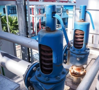
Safety valves are indispensable protective devices in pressure vessels and piping systems, widely used across industries such as petrochemicals, power generation, boilers, and pharmaceuticals. Their core function is to automatically open when system pressure exceeds a specified limit, releasing excess medium to the atmosphere or a designated collection system to prevent explosions or equipment damage caused by overpressure. Once the system pressure returns to the normal operating range, the safety valve automatically closes, ensuring continuity in the production process.
The reliability of a safety valve is directly related to equipment safety, operational stability, and even personal safety. A malfunctioning safety valve can lead not only to medium loss and environmental pollution but also to severe equipment damage and potentially fatal accidents. Therefore, a thorough understanding of common safety valve failures, their causes, and corresponding countermeasures is essential for equipment managers and maintenance engineers.
Safety Valve Opening Above the Set Pressure
Opening above the set pressure refers to a condition in which the actual opening pressure of the safety valve exceeds the maximum allowable working pressure of the equipment. This situation is extremely dangerous because it compromises the valve's overload protection function. When system pressure surpasses safe limits without triggering the valve, the equipment effectively operates without protection, greatly increasing the risk of overpressure failure in pressure vessels or pipelines.
- Excessively High Set Pressure: This is one of the most common causes. During adjustment, excessive spring compression can result in a set pressure higher than the design requirement. The solution is to readjust the spring compression strictly according to the equipment's design pressure and verify the setting with a calibrated pressure gauge to ensure it remains within the permissible range.
- Disc and Seat Adhesion: If a safety valve remains inactive for extended periods without regular inspection and maintenance, internal components may corrode, causing the disc to stick to the seat. As pressure rises, greater resistance must be overcome before the valve opens, effectively increasing the opening pressure. Preventive measures include establishing a regular maintenance schedule and performing manual venting or draining tests at least once a month to ensure the disc moves freely. Moisture protection is also important, especially in humid environments where anti-corrosion measures should be implemented.
- Internal Foreign Object Blockage: Welding slag, rust, sealing material fragments, and other debris within the pipeline may enter the safety valve and become lodged between the disc and seat or in the guide section, obstructing normal disc movement. This can significantly increase the opening pressure or even prevent the valve from opening. Thoroughly clean pipelines before installation and periodically inspect and remove debris during operation. For critical equipment, installing a filter at the valve inlet is recommended.
- External Obstructions: For deadweight or lever-type safety valves, unauthorized added weights, accumulated dust, or other external objects may hinder proper disc movement. Maintenance personnel should routinely inspect the exterior of the valve and remove any obstacles to ensure the surrounding area remains clean.
- Effect of Operating Temperature: If the set pressure is adjusted at ambient temperature but the valve operates under low-temperature conditions, material contraction may cause the actual opening pressure to exceed the original setting. Therefore, when adjusting safety valves intended for low-temperature service, the set pressure should be slightly lower than the required opening pressure to compensate for temperature effects.
- Opening Below the Set Pressure: In contrast, opening below the set pressure occurs when the safety valve opens prematurely before system pressure reaches the specified value. This failure results in unnecessary medium discharge, resource waste, and environmental pollution. Frequent opening also accelerates wear on sealing surfaces, shortening the valve's service life.
Low Set Pressure of Safety Valves
Insufficient spring compression leads to a set pressure below design requirements. Re-adjust the spring using a calibrated pressure gauge to ensure compliance with design specifications.
- Spring Aging and Reduced Elasticity: Over time, springs subjected to continuous load and corrosion may deteriorate, losing elasticity. When spring force becomes insufficient, sealing cannot be maintained even under normal operating pressure, causing premature opening. Tightening the adjustment screw may compensate for minor losses, but severely aged springs must be replaced. Establishing a replacement cycle is recommended; for critical equipment, springs should be inspected and replaced every two to three years.
- Elevated Operating Temperature: When a valve adjusted at room temperature is used in high-temperature service, thermal expansion and changes in the spring's modulus of elasticity can reduce the actual opening pressure. Therefore, the set pressure should be slightly higher during ambient adjustment. Additionally, ensure that the operating temperature does not exceed the spring's allowable limit. If leakage causes excessive temperature in the spring chamber, regrind the sealing surface to eliminate leakage and replace the spring with a high-temperature-resistant model.
- Improper Installation Angle: Deadweight and lever-type safety valves must be installed vertically. Tilting caused by improper installation or external force can disrupt force distribution on the disc, leading to premature opening or poor sealing. Reinstall the valve vertically and provide a sturdy protective guard to prevent external interference.
Safety Valve Leakage
Leakage occurs when the sealing surfaces between the disc and seat allow excessive seepage under normal working pressure. Beyond medium loss, long-term leakage can erode sealing surfaces, worsening the problem and eventually causing valve failure.
1. Leakage at the Sealing Surface
- Impurities Between Sealing Surfaces: Particles trapped between sealing surfaces can destroy the seal. Use the lifting lever to open the valve several times, allowing the flowing medium to flush out debris. If flushing is ineffective, disassemble and clean the valve.
- Sealing Surface Damage: Impact during opening and reseating, misalignment, or thermal deformation can impair sealing. Depending on the severity, repair methods include lapping or machining followed by lapping. The restored surface should be smooth, with roughness not exceeding Ra = 0.2 μm. Proper lapping techniques are essential to avoid grooves.
- Damaged Gasket: Gaskets may be damaged by debris or hard objects. Replace them with qualified components and ensure both the installation area and gasket are clean and free from contaminants.
- Bent or Misaligned Stem: Stem deformation can misalign the disc and seat, causing leakage. Reassemble or replace the stem to ensure proper coaxial alignment.
- Spring Issues: Reduced elasticity, loss of resilience, or spring fracture can weaken sealing force. Strengthen anti-corrosion and thermal insulation measures, replace failed springs promptly, and readjust the opening pressure as needed.
2. Leakage at the Valve Body Joint Surface
- Insufficient or Uneven Bolt Tightening: Improper bolt preload may compromise sealing. Tighten bolts diagonally while measuring gaps to achieve uniform clearance and apply the specified torque.
- Non-Standard Gaskets: Defects such as radial grooves, poor parallelism, or improper tooth profiles in serrated gaskets can cause sealing failure. Always use gaskets that meet standards and strictly control spare part quality during maintenance.
- Poor Flatness of Joint Surfaces: If the joint surface exceeds flatness tolerance, disassemble the valve and re-lap the surface until it meets quality standards. Clean all mating surfaces thoroughly during reassembly.
3. Other Causes of Leakage
Loss of Disc Self-Alignment Capability: Corrosion at the contact point between the stem and disc may impair the disc's ability to self-align. External disturbances to the exposed stem can shift the disc, resulting in sealing failure. Regular inspections and anti-corrosion measures are essential.
Set Pressure Too Close to Operating Pressure: If operating pressure fluctuates near or above the sealing pressure, leakage is more likely. Select an appropriately sized safety valve and set a reasonable pressure to maintain sufficient sealing specific pressure.
Frequent Popping and Chatter of Safety Valves
Frequent popping refers to repeated reopening after reseating when pressure rises slightly again. Chatter describes vibration during discharge. Both phenomena are harmful: frequent popping often leads to sealing surface leakage, while chatter causes metal fatigue and degrades mechanical performance, creating serious safety hazards.
- Excessive Spring Stiffness: If the spring is too stiff, the disc cannot reach the required lift height, resulting in insufficient discharge. Pressure continues to rise, triggering repeated openings. Replace the spring with one of suitable stiffness to ensure full lift and adequate discharge capacity.
- Improper Adjustment Ring Setting: Incorrect ring positioning may produce excessive reseating pressure or an overly large discharge area. After opening, pressure may drop sharply below operating levels, causing the disc to slam shut; if the root cause of pressure rise persists, reopening occurs. Readjust the ring to achieve an appropriate reseating pressure.
- Excessive Discharge Pipeline Resistance: Long pipelines, too many elbows, or undersized piping can create high backpressure, sharply reducing the momentum of discharged media and impairing valve performance. Minimize resistance by clearing obstructions and enlarging pipe diameter when necessary.
- Improper Valve Selection: If the valve's discharge capacity greatly exceeds the equipment's required relief capacity, pressure may drop too quickly after opening, causing oscillation. Choose a valve whose rated capacity closely matches the required relief capacity, generally slightly higher than the requirement.
Abnormal Reseating After Safety Valve Actuation
After completing pressure relief, the disc should reseat quickly and smoothly. In practice, abnormal reseating is common and typically manifests in two forms: continued pressure rise after venting and failure of the disc to reseat after discharge. If not addressed promptly, these issues can cause ongoing medium loss or loss of pressure control.
1. Continued Pressure Rise After Venting
This indicates insufficient discharge capacity. Possible causes include:
- Inadequate Valve Capacity: The selected valve cannot release excess pressure quickly enough. Replace it with one of appropriate capacity.
- Stem or Spring Problems: Misaligned stems or corroded springs may prevent the disc from lifting fully, reducing discharge. Reassemble the stem or replace the spring and implement anti-corrosion measures.
- Insufficient Vent Pipe Cross-Section: A small vent pipe limits flow. Use piping that meets the required safety discharge area.
2. Disc Fails to Reseat After Discharge
When the disc cannot reseat properly, continuous medium discharge occurs. Common causes include:
- Mechanical Binding: Bent springs, improper installation of the stem or disc, surface damage, scoring, rust, or burrs can obstruct movement. Reassemble the valve carefully, inspect all moving parts, and eliminate defects.
- Spring Fracture: A broken spring may shift after opening, preventing reseating. Replace the spring immediately and analyze the cause to prevent recurrence.
Conclusion
As the final line of defense in pressure systems, the importance of safety valves cannot be overstated. By thoroughly understanding various failure modes, their causes, and corrective measures, equipment managers can better prevent and eliminate faults, ensuring that safety valves remain in optimal working condition. In practice, the principle of “prevention first, maintenance equally important” must always be upheld. Establish a comprehensive maintenance management system, conduct regular calibration and servicing, and promptly replace aged or failed components. Only in this way can safety valves fully perform their protective function and ensure the safe and stable operation of equipment. Giving safety valves the attention they deserve, and implementing scientific management and maintenance strategies, helps prevent equipment accidents caused by valve failure and provides a solid foundation for safe industrial production.
Send your message to this supplier
Related Articles from the Supplier
Common Materials for Valve Trims
- Dec 14, 2024
Common Failures and Solutions of Gate Valves
- Nov 03, 2025
Common Problems in Pneumatic Control Valve Operation
- Feb 14, 2026
Related Articles from China Manufacturers
Two Main Kinds of Common Faults of Safety Valve
- Dec 04, 2014
Common Breakdowns and Solutions for Safety Valves
- May 26, 2017
Common Problems for API Safety Valves
- Jul 10, 2015

5 Common Safety Hazards When Operating Excavators
- Mar 18, 2024

Common Usage of Check Valve
- May 24, 2014
Common Utilized Valves in Heating System
- May 24, 2014
Related Products Mentioned in the Article
Zhejiang Kosen Valve Co., Ltd.
- https://www.kosenvalve.com/
- Business Type: Industry & Trading, Manufacturer,
Supplier Website
Source: https://www.kosenvalve.com/media-hub/common-safety-valve-failures-analysis-and-maintenance-guide.html