Angle Globe Valve Guide: Design, Uses, and Selection Tips
Angle globe valves are essential components in industrial piping systems, enabling precise flow regulation and reliable shutoff. Compared with standard globe valves, their inlet and outlet are arranged at a 90-degree angle, a distinctive structural feature that provides significant advantages in applications where space is limited or where a change in flow direction is required. This article provides a comprehensive overview of angle globe valves, covering their structural design, working principles, performance characteristics, application fields, selection criteria, and maintenance practices.
What Is an Angle Globe Valve?
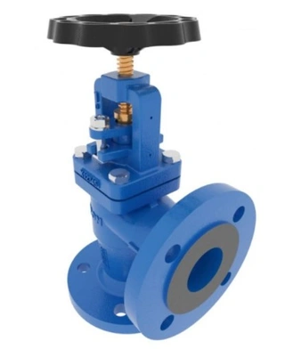
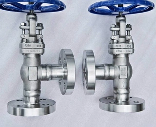
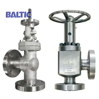
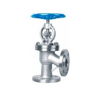
An angle globe valve is a key variant within the globe valve family, distinguished by its internal flow path, which makes a 90-degree turn inside the valve body. When fluid enters the valve through the inlet, it changes direction within the valve cavity and exits through an outlet perpendicular to the inlet.
This design offers three practical advantages:
- First, installing an angle globe valve at pipeline turning points eliminates the need for additional elbow fittings, simplifying piping layout and reducing installation complexity.
- Second, a well-designed flow path helps reduce fluid resistance, thereby minimizing energy losses within the system.
- Third, the compact structure saves installation space, making it particularly suitable for confined industrial environments.
From a structural perspective, an angle globe valve consists of several key components, including the valve body, bonnet, stem, disc, seat, packing, and operating mechanism. The valve body serves as the pressure-bearing component and is typically manufactured through casting or forging processes. The disc and seat form the sealing pair, directly determining the valve’s shutoff performance and control accuracy. The stem connects the actuator to the disc, transmitting motion and torque. The packing assembly ensures reliable sealing around the moving stem.
Working Principle and Operation Methods
The working principle of an angle globe valve is based on the relative motion between the disc and the seat.
When the operator rotates the handwheel clockwise, the stem drives the disc downward until it tightly contacts the seat, cutting off the fluid flow and closing the valve. When rotated counterclockwise, the stem lifts the disc away from the seat, allowing fluid to pass through the annular gap between them, thereby opening the valve. By adjusting the disc position, continuous flow regulation can be achieved.
This vertical movement defines the valve’s flow characteristics. When partially open, the fluid must pass through a restricted passage between the disc and seat, creating a throttling effect. This makes angle globe valves highly suitable for precise flow control applications. However, it also means they are not ideal for prolonged operation at small openings, as high-velocity flow can erode the sealing surfaces and reduce service life.
In terms of actuation, angle globe valves can be classified into four main types:
- Manual valves, operated by handwheel or lever, are simple and cost-effective, suitable for applications without frequent adjustments or remote control requirements.
- Electric valves, driven by electric actuators, enable precise stroke control and remote operation, often integrated into automated control systems.
- Pneumatic valves, powered by compressed air, offer fast response and excellent explosion-proof performance, making them ideal for hazardous environments such as petrochemical plants.
- Hydraulic valves, using hydraulic fluid as the driving medium, provide high output torque and are suitable for large-diameter, high-pressure applications.
Key Performance Characteristics of Angle Globe Valve
Angle globe valves are widely used in industrial systems due to several outstanding performance advantages.
1. High Flow Control Accuracy
The vertical movement of the disc, perpendicular to the fluid flow, allows for nearly linear flow characteristics. By adjusting the valve opening, operators can achieve precise, continuous flow regulation. This makes angle globe valves particularly effective in applications such as steam control and process proportioning.
2. Reliable Sealing Performance
Sealing reliability is critical for industrial safety. Angle globe valves feature both metal-to-metal sealing between the disc and seat and packing sealing around the stem. Precision-machined sealing surfaces ensure tight shutoff with minimal or zero leakage. Packing materials such as flexible graphite or PTFE provide durable sealing during stem movement. For hazardous media, bellows-sealed designs can be used to achieve zero stem leakage.
3. Structural Strength and Durability
The valve body is designed with sufficient wall thickness to withstand rated pressure and potential pressure surges. Common materials include carbon steel, stainless steel, alloy steel, and specialized alloys selected based on corrosion resistance and temperature requirements. Internal components such as the disc and seat are often hardened or overlaid with hard alloys to enhance resistance to erosion and cavitation.
4. Ease of Installation and Maintenance
The 90-degree design simplifies piping arrangements and reduces welding requirements. The bonnet is typically connected to the body via flanges or pressure-seal designs, allowing easy disassembly for maintenance. Standardized internal components facilitate replacement, minimizing downtime and lifecycle costs.
Key Selection Criteria for Angle Globe Valve
Selecting the right angle globe valve requires careful consideration of multiple factors.
1. Pressure and Temperature
The valve’s pressure rating must exceed the system’s maximum operating pressure with an appropriate safety margin. Temperature affects material selection; high temperatures require heat-resistant alloys, while low temperatures demand materials with good toughness.
2. Medium Characteristics
Corrosive media require compatible materials verified through corrosion data or testing. Media containing solid particles demand wear-resistant designs. High-viscosity fluids may require higher actuator torque. For hazardous media, sealing integrity is critical.
3. Flow Characteristics and Sizing
The flow coefficient (Cv or Kv) determines the valve’s capacity. Proper sizing ensures good control performance across maximum, normal, and minimum flow conditions. Ideally, the valve should operate between 30% and 70% opening for optimal control.
4. Connection Type
Flanged connections are common and easy to maintain.
Threaded connections are suitable for small, low-pressure systems.
Welded connections are used in high-pressure, high-temperature, or leak-critical applications.
Wafer connections are compact and suitable for space-constrained installations.
5. Actuation and Accessories
Manual valves may include position indicators. Electric valves require specifications for power supply and control mode. Pneumatic valves require air supply details and may include positioners, solenoid valves, and limit switches. Backup manual operation should be considered for critical systems.
6. Standards and Certifications
Valves must comply with relevant standards depending on the industry, such as those for petrochemical, power, or nuclear applications. Certifications may include CE, SIL, or other project-specific requirements.
Main Application Fields of Angle Globe Valve
Angle globe valves are used across a wide range of industries, playing critical roles in various applications.
1. Oil and Gas Industry
In upstream operations, angle globe valves are used in wellhead equipment and gathering pipelines for flow and pressure control. In refining and petrochemical plants, they are installed at inlets and outlets of reactors, heat exchangers, and separators. Due to high pressure, flammable media, and corrosive components like hydrogen sulfide, these valves are typically made from high-strength alloy steels and comply with international standards.
2. Power Generation Industry
Angle globe valves are widely used in thermal power plants for main steam, reheat steam, feedwater, and cooling systems. Valves in main steam lines must withstand high temperature and pressure, often using chromium-molybdenum steel bodies and hard-faced sealing surfaces. In nuclear power plants, nuclear-grade angle globe valves are designed to meet stringent safety and reliability requirements.
3. Chemical Industry
Chemical processing environments are highly diverse and demanding. For strong corrosive media such as sulfuric acid, hydrochloric acid, or nitric acid, materials like Hastelloy, titanium, or zirconium are required. For viscous or slurry media, special flow paths or disc designs are necessary to prevent clogging. These valves must also handle temperature fluctuations and pressure variations.
4. Water Treatment Industry
In municipal water supply, wastewater treatment, and industrial water systems, angle globe valves regulate flow and control liquid levels. They are commonly made from ductile iron or stainless steel, with soft sealing materials such as rubber or PTFE to ensure reliable sealing and easy operation.
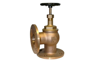
5. Marine and Offshore Engineering
Angle globe valves are used in bilge systems, ballast systems, fuel systems, and steam systems on ships and offshore platforms. Their compact design is ideal for limited spaces. Offshore applications require additional considerations for seawater corrosion and mechanical vibrations.
Angle Globe Valve Installation and Operation Considerations
Proper installation is essential for optimal valve performance. Before installation, verify specifications, inspect for damage, and conduct pressure testing if necessary. Pay attention to flow direction markings, as some designs may have directional requirements.
Ensure adequate space for operation and maintenance. During welding, protect sealing surfaces from damage. After installation, clean the pipeline to remove debris. Before commissioning, perform full stroke tests to ensure smooth operation.
Avoid using angle globe valves at very small openings for extended periods, as this can cause erosion. For infrequently used valves, periodic operation helps prevent sticking. Minor leakage at the packing can be addressed by tightening the gland, but excessive tightening should be avoided.
Angle Globe Valve Maintenance and Servicing
Routine maintenance extends the service life of angle globe valves. Regular inspections should include checking for external leakage, monitoring packing condition, and listening for abnormal noises.
Periodic maintenance involves disassembling the valve, cleaning internal components, inspecting sealing surfaces, checking stem condition, replacing worn packing, lubricating moving parts, and verifying fastener integrity.
Minor damage to sealing surfaces can be repaired by lapping. Severe damage requires replacement of the disc or seat. After repairs, sealing performance tests must be conducted before returning the valve to service.
For valves in long-term storage, periodic operation ensures that moving parts remain functional.
Conclusion
Angle globe valves, with their unique 90-degree flow path and excellent control capabilities, play a vital role in industrial fluid control systems. From oil and gas to power generation, chemical processing, water treatment, and marine engineering, they provide reliable flow regulation and isolation under a wide range of operating conditions.
Understanding their structure, working principles, and performance characteristics, along with proper selection, installation, and maintenance practices, is essential for ensuring long-term, stable operation. By applying these best practices, angle globe valves can significantly enhance system safety, efficiency, and reliability in modern industrial applications.
Send your message to this supplier
Related Articles from the Supplier
Related Articles from China Manufacturers


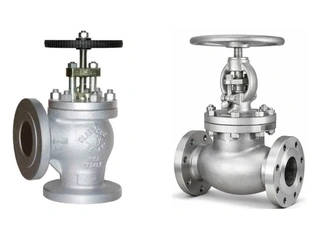
Angle Globe Valve vs. Standard Globe Valve
- May 09, 2026
Angle Type Globe Valve
- Nov 02, 2020
EN13709 Angle Globe Valve: Durable Flow Control
- Oct 28, 2024
What is Angle Type Globe Valve
- Oct 18, 2024
Related Products Mentioned in the Article
Zhejiang Kosen Valve Co., Ltd.
- https://www.kosenvalve.com/
- Business Type: Industry & Trading, Manufacturer,
Supplier Website
Source: https://www.kosenvalve.com/media-hub/angle-globe-valve-guide-design-uses-and-selection-tips.html