Guide to Oil & Gas Separators: Principles, Types, and Uses
Oil & gas separators are indispensable key equipment in the process of oil and natural gas extraction and processing. Simply put, they are mechanical devices specifically used to separate oil, gas, water, and other different components mixed together.
When crude oil is extracted from underground, it is not in a pure state as we might imagine. In its natural state, crude oil is usually mixed with natural gas, formation water, and various solid impurities. If these are directly transported or processed without separation treatment, it will not only affect product quality but may also damage downstream equipment and even create safety hazards. The role of oil & gas separators is to separate these mixed substances according to their respective physical properties, so that each component can be properly utilized.
Depending on processing requirements, oil & gas separators are divided into two-phase separators and three-phase separators. Two-phase separators mainly separate liquid and gas, while three-phase separators can simultaneously separate oil, gas, and water. The specific size and structural form of the equipment are designed according to actual operating conditions, ranging from small mobile units to large fixed equipment, which are widely used.
Working Principle of Oil & Gas Separators
The working process of oil & gas separators is not complicated. The core principle is to use the differences in physical properties such as density and viscosity between oil, gas, and water to achieve natural stratification under gravity. The entire separation process can be divided into four main stages:
1. Inlet Buffering
The mixed fluid first enters the separator through the inlet device. The key function of the inlet design is to dissipate and reduce the energy of the high-speed incoming well stream so that the fluid can be evenly distributed inside the separation chamber instead of directly impacting the inner wall of the equipment. The design of this stage directly affects the subsequent separation effect.
2. Primary Separation
This is a specific area inside the separator surrounding the inlet. Here, liquid and gas achieve initial separation. Through mechanical components such as guide plates or baffles, most of the liquid is directed into the lower liquid accumulation zone, and larger droplets immediately begin to fall under gravity. This stage can remove most of the free liquid.
3. Secondary Separation
The area located after the primary separation zone and between the liquid accumulation area and the mist eliminator is called the secondary separation section. Since the cross-sectional area of the vessel here increases significantly, the flow velocity of gas and liquid is greatly reduced. After the velocity decreases, smaller liquid particles have enough time to continue settling downward under gravity.
In vertical separators, gas flows upward, generating upward resistance to droplets. Larger droplets settle because gravity is greater than resistance, while very fine droplets may be carried away by the gas flow and need to be removed in subsequent stages.
In horizontal separators, the gas flow direction is perpendicular to gravity and does not hinder droplet falling. The movement trajectory of droplets is usually diagonal. This design allows horizontal separators to handle larger gas volumes under the same diameter.
4. Fine Separation
After the previous two stages, the gas may still contain fine liquid droplets. The function of the mist eliminator is to capture these fine droplets and make them coalesce into larger droplets before settling. Common mist eliminators include knitted wire mesh types, vane types, and centrifugal types. When the gas flows through the complex channels of the eliminator, it continuously changes direction. Fine droplets collide and coalesce, gradually increasing in size, and finally overcome gas flow resistance and fall into the liquid accumulation zone.
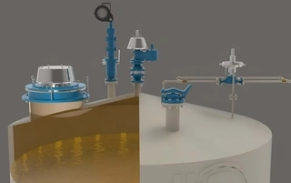
Liquid Handling and Discharge
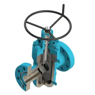
All separators are equipped with a dedicated liquid accumulation area used to collect liquids from the primary separation section, secondary separation section, and mist eliminator. This area is usually equipped with a liquid level controller, drain valve, control valve, and liquid level sight glass.
The liquid needs to stay in the accumulation area for a certain period of time to allow dissolved gas to fully escape. In two-phase separation, the liquid residence time is usually designed to be about 1 minute. In three-phase separation, in order to achieve oil-water separation at the same time, the residence time is usually extended to 3 minutes.
The liquid outlet is usually located far away from the inlet so as to extend the residence time of liquid in the vessel and promote gas release. The outlet is also equipped with anti-vortex baffles or adopts a siphon-type drainage structure to prevent vortex formation from causing gas to be re-entrained into the liquid and discharged.
Main Types of Oil & Gas Separators
According to structural configuration and operating characteristics, the oil and gas separators commonly used in industry are mainly classified into the following types:
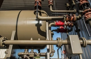
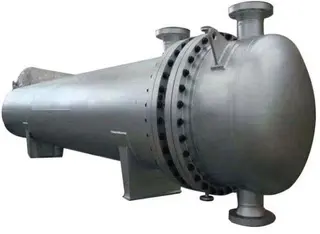
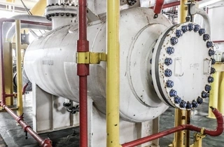
1. Horizontal Separators
The main body of a horizontal separator is a horizontally placed cylindrical pressure vessel. The biggest advantage of this structure is a large gas-liquid contact area, making it suitable for handling large flow rates of liquid and gas.
Horizontal separators are usually used in three-phase separation conditions and can simultaneously separate oil, gas, and water. Due to horizontal arrangement, liquid forms a longer flow path at the bottom of the vessel, which is beneficial for oil-water stratification. However, horizontal separators usually use about half of the space for liquid accumulation, so compared with vertical structures, their buffering capability for instantaneous flow fluctuations is relatively weaker.
Inside horizontal separators, the inlet baffle usually adopts a flat or dish-shaped structure, which throws incoming liquid against the inner wall of the shell, forming a thin film and promoting dissolved gas release.
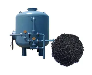
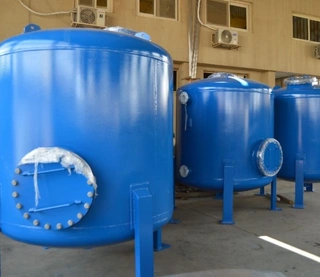
2. Vertical Separators
Vertical separators adopt a vertically placed cylindrical structure, occupying a small footprint and having a compact structure, making them suitable for installations with limited space.
This type of separator is more suitable for low flow conditions and can be used for both two-phase separation and, under certain conditions, three-phase separation. A notable feature of vertical separators is that a baffle is usually installed between the liquid accumulation section and the secondary separation section, which can effectively prevent liquid from being re-entrained by gas flow and reduce interference of liquid level fluctuations on the liquid level control system.
In vertical structures, inlet guide devices force the liquid to change direction and flow toward the shell of the vessel, forming a thin film on the surface of the shell, allowing dissolved gas to be released.
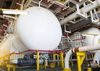
3. Spherical Separators
Spherical separators use spherical pressure vessels. This structure has unique advantages in resisting internal pressure. The spherical geometry makes stress distribution more uniform, so it is especially suitable for high-pressure conditions.
Although the manufacturing process of spherical separators is relatively complex and the cost is also higher, in some high-pressure application scenarios, their structural strength advantages make them an irreplaceable choice.
Practical Benefits of Using Oil & Gas Separators
In oil and gas production and processing, the use of separators brings many practical benefits:
1. Improving Production Efficiency
By timely separating oil, gas, and water, each component can enter its corresponding processing flow, avoiding efficiency losses caused by mixed transportation. Natural gas can directly enter the gas gathering system, crude oil enters storage or processing links, and produced water is separately treated.
2. Protecting Downstream Equipment
Removing water and solid impurities from crude oil can significantly reduce corrosion and wear of subsequent pumps, pipelines, and processing equipment, extend equipment service life, and reduce maintenance costs.
3. Improving Product Quality
Separated crude oil is purer, meets commercial crude oil quality standards, and has better price and competitiveness in the market.
4. Environmental Protection
Through effective separation, wastewater can be centrally treated to meet discharge standards or reinjected, reducing the risk of oil-containing wastewater pollution to the environment. At the same time, recovery and utilization of associated gas also reduces greenhouse gas emissions.
Common Problems and Solutions
In actual operation, oil & gas separators may encounter the following common problems:
- Foaming Problem: Some crude oils contain natural surfactants that easily form stable foam layers, affecting separation performance. Solutions include adding defoamers or adjusting operating temperature and pressure parameters.
- Emulsification Problem: When oil-water mixtures form stable emulsions, gravity separation alone cannot achieve effective separation. In this case, demulsifiers can be added to break the emulsion state and promote oil-water stratification.
- Carryover Phenomenon: When gas flow velocity is too high, liquid may be carried into the gas outlet, causing liquid loss and downstream equipment problems. Solutions include adjusting flow control, optimizing temperature parameters, or checking the working condition of the mist eliminator.
Conclusion
Although oil & gas separators may seem like simple pressure vessels, their internal structural design and working principles reflect a sophisticated combination of fluid mechanics, thermodynamics, and mechanical engineering.
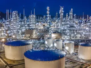
From wellhead separators at oil extraction sites to three-phase separation systems in large refineries, and even circulating protection equipment in industrial refrigeration systems, oil & gas separators play an irreplaceable role in ensuring production efficiency, product quality, and equipment safety.
With the development of oil and gas resources toward deep formations, deep seas, and unconventional fields, higher requirements are being placed on separation technology. More efficient, more compact, and more intelligent separation equipment will continue to drive technological progress in the oil and gas processing industry. For technical personnel engaged in related work, a deep understanding of separator working principles and operational key points is the foundation for ensuring safe and efficient production operations.
Send your message to this supplier
Related Articles from the Supplier

Complete Guide to Floating Head Heat Exchanger
- Mar 24, 2025
Complete Guide to Storage Tank Venting Systems
- Mar 30, 2026
Related Articles from China Manufacturers
Guide to Selecting Oil & Gas Three-Phase Separators
- Apr 07, 2026
Guide to Safe Operation of Crude Oil Storage Tanks
- Dec 30, 2025
A Guide to Diesel Generator Set Engine Oil Change
- Sep 03, 2025
Guide to Seal Oil Flushing for Generator Set
- Dec 01, 2024
Guide to Pipe Bend Manufacturing Processing
- Sep 03, 2025
Related Products Mentioned in the Article
DFC Tank Pressure Vessel Manufacturer Co., Ltd.
- http://www.dfctank.com/
- Business Type: Manufacturer,
Supplier Website
Source: https://www.dfctank.com/news/guide-to-oil-gas-separators-principles-types-and-uses.html