Guide to Multi-Directional Die Forging Technology
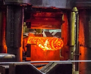
Multi-directional die forging is an advanced metal forming process primarily used to manufacture precision forgings with complex geometries. The process is carried out on a multi-directional die forging hydraulic press, utilizing a combined die with multiple parting surfaces. In a single pressing stroke, the heated metal billet is shaped into the desired form. One of the most notable features of multi-directional die forging is its ability to produce complex components with no flash or minimal flash, as well as little to no draft angle.
Unlike traditional single-direction die forging, multi-directional die forging overcomes the limitation of forming force from only one direction. Pressure can be applied simultaneously from multiple directions, allowing the metal to flow fully within the die cavity and fill intricate features. This method is particularly suitable for manufacturing parts with multi-directional holes, bosses, or branch-like structures, such as high-pressure valve bodies, pipe fittings, and aerospace structural components.
Features of Multi-Directional Die Forging Hydraulic Presses
The multi-directional die forging hydraulic press is the core equipment that enables this process. Compared with conventional die forging presses, it features a more complex structure and broader functionality.
1. Multi-Cylinder Configuration System
A standard multi-directional die forging hydraulic press is equipped not only with a vertical working cylinder but also with two or four horizontal working cylinders. Additionally, a piercing cylinder is installed at the center of the crossbeam or moving crossbeam. This configuration provides the press with four or six independent slides, each capable of operating individually or in coordination.
The advantage of this multi-cylinder design lies in its ability to apply pressure simultaneously or sequentially from mutually perpendicular directions. It supports various forming modes, including vertical parting, horizontal parting, and combined vertical–horizontal parting. This flexibility allows the equipment to adapt to forging requirements for components of different shapes.
2. Pressing Capacity Characteristics
Typically, the pressure of the vertical working cylinder is greater than that of the horizontal cylinders. This characteristic is crucial when selecting a parting method. For large forgings that require substantial clamping force, horizontal parting is often preferred because it enables the vertical cylinder to provide stronger mold-closing force, ensuring tight die closure and preventing flash formation.
Four Basic Structures of Multi-Directional Forging Dies
Dies are central to the multi-directional forging process, and their structural form directly determines forging quality and process feasibility. Based on the position and combination of parting surfaces, multi-directional forging dies can be classified into four primary types.
1. Horizontal Parting Die Structure
In this structure, the parting surface is parallel to the horizontal plane. The forging is primarily formed through bidirectional extrusion by horizontal working plungers.
Two die cavities are secured to the upper and lower die holders using wedge plates and screws. Two horizontal punches are mounted on the clamping seats of the press’s horizontal plungers. Alignment accuracy is ensured by the guiding sections of the punches as well as guide pillars and bushings when the dies close.
Horizontal parting is the most widely used structure in multi-directional forging, particularly suitable for forgings with deep holes at both ends. It is also applicable when only one end contains a deep hole. For large forgings requiring significant clamping force, horizontal parting is typically the preferred solution.
2. Vertical Parting Die Structure
The parting surface in a vertical parting die is perpendicular to the horizontal plane, and forging is mainly achieved through downward extrusion by the vertical plunger.
In this configuration, one end of each horizontal push rod connects to the plunger clamping seat of the horizontal working cylinder, while the other end is pinned to the die cavities. The rods drive the two die halves along the base plate to open and close the die.
A locating block at the center of the base plate ensures precise positioning, keeping the punch aligned with the cavity center. Guide pins between the die halves prevent misalignment during closure. Vertical parting is typically used when three or four die blocks must open and close within the same plane.
3. Combined Parting Die Structure
Combined parting dies incorporate both vertical and horizontal parting surfaces. Two lower die blocks form the vertical parting, while together with the upper die they create a horizontal parting, resulting in a complex combined structure. A guide hole is located at the center of the upper die to direct the punch during extrusion.
This structure is ideal for extremely complex forgings that require simultaneous forming from multiple directions, fully leveraging the advantages of multi-directional die forging.
4. Special Die Structures
When the three basic structures cannot meet forging requirements—or when equipment limitations must be compensated—special die designs are necessary. For example, fork-shaped or other customized structures may be adopted when unique vertical opening motions are required or when the forging geometry is highly irregular.
Key Considerations in Multi-Directional Die Design
Die design directly affects forging quality and die service life. Several critical factors must be considered.
1. Cavity Layout
When arranging cavity positions, it is important to recognize that the center of die-opening force often does not coincide with the geometric center of the cavity. Designers should align the opening-force center as closely as possible with the clamping-force center to avoid localized separation and flash formation. Proper cavity placement is particularly important for asymmetric forgings with complex bosses or branch-like features.
2. Die Guiding and Positioning
The guiding and centering functions of die guidance systems are essential for ensuring dimensional accuracy. Mating surfaces should provide positioning capability, and dedicated guiding components must be incorporated to prevent misalignment.
Cylindrical guide pins are commonly used. One pin is press-fitted into one die half, while a guide hole—or a bushing pressed into the hole—is machined into the mating half. The typical clearance is about 0.5 mm, and most dies require two guide pins. When three die blocks are combined, cylindrical pins with guide grooves may be used.
3. Guide Length and Concentricity
The die's guide holes must be sufficiently long to maintain concentricity of the horizontal punches during forging. Insufficient guidance can cause punch deflection, negatively affecting the dimensional accuracy and surface quality of internal holes.
4. Punch-to-Die Clearance
A certain clearance must be maintained between the punch and the die. Factors influencing this clearance include the concentricity of the horizontal cylinders, the precision of die and worktable heights, deformation of the moving crossbeam, elastic die deformation, and installation misalignment of the punch.
Excessive clearance may produce longitudinal burrs, while insufficient clearance can accelerate wear or cause seizure. Proper clearance ensures forging quality and extends die life.
5. Punch Dimension Calculation
The working dimensions of the punch are determined based on the forging’s internal diameter. Key factors include the nominal internal diameter, the material’s linear shrinkage coefficient, and tolerance requirements. Calculations must ensure that the cooled forging meets drawing specifications.
Special Design Considerations for Deep-Hole Forgings
Shear-bearing surface design: When extracting a punch from a deep hole, a certain pulling force is required, which may deform the forging. Therefore, sufficient shear-bearing surfaces must be designed between the forging and the cavity to prevent tearing or distortion during punch removal.
Dimensional relationships between processes: For complex forgings requiring multiple operations, critical inter-process dimensions must be carefully defined. The opening width formed in the previous step must be greater than that of the semi-finished part in the next step. This ensures that forming cores can be inserted smoothly and removed easily—an essential principle in multi-stage multi-directional forging.
Rigidity Design of Horizontal Push Rods
In vertical parting structures, horizontal push rods drive die opening and closing. Insufficient rigidity can lead to deformation under high pressure, resulting in poor die closure and flash defects. Therefore, push rods must be designed with adequate stiffness to maintain precise positioning under maximum load.
Rigidity design should consider working load, stroke length, and material strength. High-quality alloy steels are typically used, combined with appropriate heat treatment to enhance strength and wear resistance.
Selection of Die Materials
Because multi-directional forging presses operate relatively slowly, dies remain in contact with hot forgings for extended periods, experiencing high temperatures and repeated thermal cycling. These conditions can cause surface fatigue cracks, and extrusion-dominated deformation leads to significant wear.
As a result, die materials must offer high hardness and heat resistance, strong hot-hardness retention, excellent resistance to thermal fatigue, and good thermal conductivity for rapid heat dissipation.
Common materials include hot-work tool steels such as H13 and 3Cr2W8V. With proper heat treatment, these materials can meet the demanding requirements of multi-directional forging.
Billet Pre-Treatment for Multi-Directional Forging
For complex forgings with large deformation, billet pre-treatment is essential for ensuring forming quality. Parts with significant bending deformation are especially prone to cracking during forming, making pre-treatment of cut round steel billets necessary.
The recommended method is localized low-temperature annealing at the bending areas. This process relieves internal stresses generated during cold drawing and enhances plastic deformation capacity, preventing bursting during subsequent forming.
Full high-temperature annealing should be avoided, as it easily produces oxide scale on the billet surface. Such scale is difficult to remove and can negatively affect surface quality—particularly for products requiring electroplating.
In practice, simplified annealing equipment can be used. A coke furnace with a small blower at the air inlet increases oxygen supply and fire intensity. Placing an iron plate with multiple 25–30 mm holes over the furnace opening allows the billet’s forming area to be heated for several minutes. This method reduces investment in high-frequency electric furnaces, lowers energy consumption, simplifies production setup, shortens preparation cycles, and helps reduce product costs.
Technical Advantages of Multi-Directional Die Forging
The key reason multi-directional die forging can produce shapes that are difficult—or impossible—for other forging methods lies in its dies with multiple parting surfaces. This design allows metal to flow simultaneously or sequentially from several directions, filling complex cavities and forming features such as multi-directional holes, bosses, and branches.
Its main advantages include:
Capability to produce extremely complex forgings, especially parts with holes in multiple directions
High dimensional accuracy with little or no flash and minimal draft, reducing subsequent machining
High material utilization due to the absence of large flash allowances
Dense internal structure with well-distributed metal flow lines and excellent mechanical properties
Conclusion
Multi-directional die forging is a technologically advanced forming process with broad application prospects. Mastering this technology requires a thorough understanding of equipment characteristics, die structures, and critical design principles. Through optimized die design, strict process control, and appropriate billet pre-treatment, manufacturers can produce high-quality complex forgings that meet the demands of high-end industries such as aerospace, energy, and automotive manufacturing. As manufacturing technologies continue to evolve, multi-directional die forging is expected to expand into even more fields and applications.
Send your message to this supplier
Related Articles from the Supplier
Guide to Multi-Directional Die Forging Technology
- Feb 04, 2026
Guide to Liquid Die Forging Technology
- May 20, 2025
Guide to Nickel-Based Alloy Open Die Forging
- Dec 09, 2025
Guide to Metal Forging with Presses
- Mar 17, 2026

Comprehensive Guide to Forging Cleaning Methods
- Dec 11, 2024
A Complete Guide to Forging Process of Bearing Rings
- Jun 25, 2025
Related Articles from China Manufacturers
A Guide to Media Selection for Multi-Media Filters
- Jul 25, 2024
Guide to Non-Ferrous Metal Forging Process
- Nov 06, 2025
Guide to Aluminum Alloy Forging Technology
- Nov 13, 2025

Related Products Mentioned in the Article
![A Guide to Computer User Support for Help Desk [Book]](https://img.jeawincdn.com/resource/upfiles/153/images/products/custom-full-color-printing/custom-catalogs/resize/3f25b1a83689330016a4063627d10c04/CC002-A-Guide-to-Computer-User-Support-for-Help-Desk-Book-320x320.webp)

Supplier Website
Source: http://www.creatorcomponents.com/news/guide-to-multi-directional-die-forging-technology.html