What is a Valve Cage in a Control Valve
In industrial piping systems, a control valve is a key device used to regulate the flow rate, pressure, and temperature of fluids such as liquids, gases, or steam. Inside many modern control valves, there is a very important internal component known as the valve cage. This article provides a clear and easy-to-understand explanation of the valve cage, including its functions, structural types, selection methods, and its application in cage-guided control valves.
Basic Functions of a Valve Cage
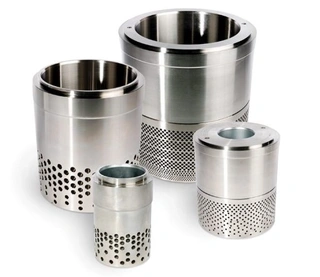
A valve cage is a cylindrical component installed inside the body of a control valve. It is usually made of metal and features variously shaped and sized openings on its surface. The valve cage plays several important roles in a control valve, mainly in the following five aspects.
1. Guiding Stable Movement of the Valve Plug
The valve plug is the moving part in a control valve that changes the size of the flow passage. The valve cage surrounds the plug and provides precise guiding support. When the plug moves up and down, the cage ensures it stays aligned along the same axis without lateral vibration or jamming.
This stable guiding function prevents vibration, sticking, or deviation during operation, ensuring reliable opening and closing performance of the valve.
2. Forming the Flow Passage
The wall of the valve cage is machined with different types of openings, such as circular holes, square windows, or trapezoidal slots. As the valve plug moves, the overlapping area between the plug and the cage openings changes, thereby adjusting the effective flow area.
By designing different shapes and distributions of these openings, different flow characteristics can be achieved, such as:
Linear flow characteristic (flow proportional to stem travel)
Equal percentage flow characteristic (flow change rate proportional to current flow)
3. Balancing Pressure on Both Sides of the Plug
Under high differential pressure conditions, a large pressure difference exists between the upstream and downstream sides of the valve plug. This creates an unbalanced force that pushes the plug in one direction. If this force becomes too large, the actuator must generate significant force to control the plug position.
The valve cage is designed with balancing holes or pressure-equalizing structures that redirect part of the high-pressure fluid to the low-pressure side. This reduces the pressure difference acting on the plug.
The direct benefits include:
Smaller actuator size requirement
Lower equipment cost
Improved system stability and control accuracy
4. Reducing Fluid Noise
When gas or steam flows at high speed through a valve, it generates significant noise. This noise not only affects the working environment but may also cause vibration damage to internal valve components.
The valve cage reduces noise by distributing high-speed flow into multiple small jets through its openings. This converts concentrated flow into dispersed flow, reducing velocity and turbulence.
Specially designed low-noise cages can also shift noise frequency from low-frequency ranges (more sensitive to human hearing) to higher frequencies, reducing perceived noise levels.
5. Preventing Cavitation Damage
Cavitation is a destructive phenomenon that occurs in liquid service under high pressure drop conditions. When liquid flows through a throttling point, pressure drops sharply. If the pressure falls below the liquid’s vapor pressure, vapor bubbles form. When these bubbles move to a higher pressure region, they collapse violently, producing shock waves that damage valve surfaces.
The valve cage prevents cavitation through multi-stage pressure reduction. Instead of a single large pressure drop, the pressure is reduced gradually in multiple stages. Each stage has a small pressure drop, ensuring the pressure does not fall below vapor pressure.
As a result, cavitation is avoided, protecting the valve and extending its service life.
Main Types of Valve Cages in Control Valves
Based on different operating conditions, valve cages can be classified into two main categories: general-purpose cages and severe-service cages.
1. General-Purpose Valve Cages
General-purpose cages are suitable for clean media and medium differential pressure applications. They mainly include the following two types.
Window-Type Cage: The window-type cage has large window-shaped openings on the cylinder wall, usually square or trapezoidal in shape. It is relatively simple to manufacture and has a lower cost. Because the openings are large, flow resistance is low and flow capacity is high. This type is widely used in general industrial applications where the medium is clean and pressure drop is not high.
Drilled Hole Cage: The drilled hole cage contains many evenly distributed small circular holes on the cylinder wall. Compared to the window-type design, it provides more precise flow control and more stable flow characteristics. In addition, because more metal is retained in the structure, it has higher mechanical strength and can withstand higher pressures. It is suitable for applications requiring high control accuracy and stability.
2. Severe-Service Valve Cages
Severe-service cages are specially designed for demanding conditions such as high pressure drop, cavitation, or high noise environments.
Anti-Cavitation Cage: The anti-cavitation cage is used in high differential pressure liquid applications. Its core design is a multi-stage pressure reduction structure. As the fluid passes through the cage, it goes through several throttling stages. Each stage only reduces a small portion of the pressure. Although the total pressure drop is large, each individual stage remains above the liquid’s vapor pressure. This prevents cavitation bubble formation and effectively protects the valve from damage, significantly extending service life.
Noise-Reducing Cage: The noise-reducing cage is designed for gas and steam applications. It contains a large number of extremely fine flow channels on the cage wall. When high-pressure gas passes through these channels, it is divided into many small streams, significantly reducing flow velocity. At the same time, the fine channels shift noise frequencies into higher ranges that are less noticeable to the human ear. This type of cage is widely used in systems with strict noise control requirements, such as plants near residential areas or facilities with strict occupational hearing protection standards.
Key Selection Criteria for Control Valve Cages
When selecting a control valve in real applications, the choice of valve cage must consider several important factors.
1. Type of Medium
The first step is to identify whether the medium is liquid, gas, or steam. Liquids require attention to cavitation risk, while gases and steam require focus on noise control.
2. System Pressure Differential
Pressure drop is a key factor in cage selection. For low differential pressure conditions, general-purpose cages are usually sufficient.
However, in high differential pressure applications, anti-cavitation or noise-reducing cages must be used. Otherwise, issues such as high noise, severe vibration, and short valve lifespan may occur.
3. Cavitation Risk
For liquid service, it is necessary to calculate whether the pressure at the throttling point may fall below vapor pressure. If cavitation risk exists, an anti-cavitation cage must be selected.
4. Noise Control Requirements
If the plant has strict noise limitations or if the valve is installed near residential areas, a noise-reducing cage should be used.
5. Severity of Operating Conditions
For media containing solid particles, wear-resistant cage materials should be selected. For high-temperature and high-pressure conditions, materials and structures capable of withstanding thermal stress must be used.
Ignoring these factors—for example, using a standard window-type cage in a high-pressure cavitation condition—can lead to:
- Significant noise increase
- Severe system vibration
- Erosion damage due to cavitation
- Reduced valve service life
Therefore, correct cage selection is critical for improving control accuracy, operational stability, and equipment lifespan.
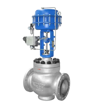
Application of Valve Cage in Cage-Guided Control Valves
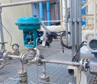
A cage-guided control valve is a type of control valve that uses a valve cage as the guiding structure for the valve plug. It is widely used in industries such as petroleum, natural gas, power generation, chemical processing, and water treatment.
1. Working Principle
In a cage-guided control valve, the valve plug moves up and down inside the cage. As the plug moves, the opening area of the cage changes, thereby regulating flow.
The cage not only provides throttling control but also ensures stable guiding support, preventing lateral forces on the stem. This is a major advantage over traditional stem-guided structures.
By replacing cages with different opening designs, the flow characteristics of the valve can be easily adjusted to meet different process requirements.
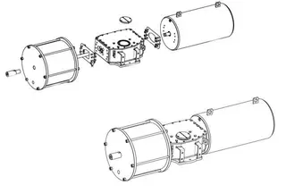
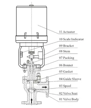
2. Structural Composition
A cage-guided control valve mainly consists of three parts:
- Valve trim (plug, cage, seat)
- Valve body
- Actuator
The valve trim determines valve performance and is usually made of corrosion-resistant, anti-cavitation, and erosion-resistant materials. The valve body provides the flow path and houses internal components. Some designs use an “S-shaped” flow passage to reduce flow resistance.
The actuator is commonly a multi-spring pneumatic diaphragm type, offering stable output force and reliable response.
3. Main Application Areas
In the oil and gas industry, cage-guided control valves are used for pipeline pressure regulation, separation systems, and wellhead control.
In the power industry, they are used in steam systems, cooling water systems, and boiler feedwater regulation.
In the chemical industry, they control flow in reactors, heat exchangers, and separation equipment.
In water treatment systems, they are used for flow and pressure management in filtration systems, pumping stations, and water supply networks.
4. Maintenance and Calibration
To ensure long-term stable operation, the following maintenance tasks should be performed regularly:
Inspect valve body, trim, and actuator for wear, corrosion, or damage
Clean internal components to prevent blockage
Lubricate moving parts
Replace aged sealing components
Calibrate valve at 0%, 25%, 50%, 75%, and 100% stroke positions to ensure accurate control performance
Conclusion
The valve cage is a small but extremely important component in a control valve. Through guiding the valve plug, forming flow passages, balancing pressure, reducing noise, and preventing cavitation, it significantly enhances valve performance and reliability. When selecting a valve cage, factors such as medium type, pressure differential, cavitation risk, and noise requirements must be carefully considered. Choosing the correct cage type improves control accuracy, operational stability, and equipment lifespan while reducing maintenance costs. In modern industrial systems, proper valve cage selection is not just a design detail—it is a key factor in ensuring safe, efficient, and long-term valve operation.
Send your message to this supplier
Related Articles from the Supplier
What is a Valve Cage in a Control Valve
- May 27, 2026
What is a Full-Function Lightweight Control Valve?
- Sep 09, 2024
What Is a Low-Load Butterfly Control Valve?
- Oct 27, 2025
What is a Scotch Yoke Pneumatic Actuator?
- Sep 15, 2024
What is Electric Valve Opening Control?
- Sep 08, 2025
Related Articles from China Manufacturers
What is a Cage Guided Globe Control Valve?
- Dec 31, 2024
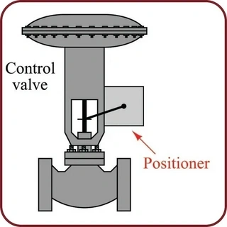
What is a Valve Positioner, and How Does It Work
- May 29, 2026
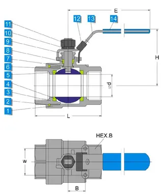
What Is A Ball Valve
- May 25, 2017
What is a gate valve?
- Feb 14, 2019
What is a check valve?
- Feb 28, 2019
What is a butterfly valve?
- Mar 07, 2019
What is a Bellows Seal Globe Valve?
- Nov 15, 2024
What is a Globe Valve Used For?
- Sep 02, 2025
Related Products Mentioned in the Article
Supplier Website
Source: https://www.valvecontrol.cn/news/what-is-a-valve-cage-in-a-control-valve.html