High-Pressure Ball Valve Design: Strength and Sealing Analysis
Abstract
Ball valves, as essential components for regulating fluid flow, are widely employed across modern industrial sectors. However, under high-pressure conditions, their structural integrity and sealing performance are severely challenged, and conventional designs often struggle to meet the dual requirements of high strength and reliable sealing. This paper investigates the structural integrity and sealing performance of ball valves under high-pressure conditions. Following relevant standards, the overall structural design and dimensional calculations of key components are performed, and finite element simulations are conducted on the valve body and ball. The results indicate that the stress distribution in both the valve body and the ball is uniform and remains below the materials’ allowable stress limits, confirming the valve’s structural integrity. Additionally, the end sealing assembly exhibits a uniform and well-balanced sealing pressure distribution, confirming its excellent sealing performance. This study offers a robust theoretical basis for the design and optimization of high-pressure ball valves.
1. Overview
In modern industrial systems, valves are essential components for controlling fluid pressure and flow, with widespread applications in industries such as petroleum, natural gas, chemical processing, and power generation. Among these, ball valves are the preferred choice for high-pressure applications thanks to their distinct advantages, including fast operation, excellent sealing, user-friendly handling, and minimal flow resistance. However, under extreme high-pressure conditions, ball valves face exceptionally stringent demands for both sealing performance and structural strength—two critical factors that directly affect their reliability and operational safety. As industrial processes advance toward higher pressures and greater flow rates, ensuring sufficient sealing and structural integrity in ball valves has become an increasingly critical challenge. In the closed position, the valve’s sealing surfaces are subjected to immense pressure differentials. Even slight imperfections in the sealing design or inadequate material strength can result in serious leakage or even catastrophic system failure. Conversely, when the valve is open, the intricate flow patterns and high-pressure environment created by large flow rates place significant demands on the valve’s overall structural strength. If the valve is poorly designed, localized stress concentrations can occur, leading to fatigue failure or plastic deformation, which in turn compromises the valve’s performance and reduces its service life. Against this backdrop, this study investigates the structural strength and sealing performance of ball valves under high-pressure operating conditions. By combining theoretical analysis with numerical simulation, this research aims to assess and optimize the valve’s structural integrity and sealing performance. The study covers two primary aspects: (1) the overall structural design and dimensional calculations of key valve components, and (2) finite element-based static simulations of the valve body and ball to evaluate stress distribution and sealing performance.
2. Structural Design
2.1 Valve Body and Bonnet Assembly Design
The technical specifications for the high-pressure ball valve examined in this study are summarized in Table 1. The valve is designed to operate at a working pressure of 45 MPa, with a nominal pressure set at 1.5 times the working pressure, i.e., 67.5 MPa. According to GB/T 1048–2019, “Definition and Selection of Nominal Pressure for Piping Components,” this valve falls within the Class 4500 series and is assigned a nominal pressure rating of PN630. Therefore, the primary design reference for this valve is ASME B16.34, “Flanged, Threaded, and Welded End Valves,” which specifies a minimum internal diameter of 57.2 mm. In accordance with GB/T 13927–2022, “Industrial Valves — Pressure Testing,” this valve is classified as a metal-seated type with a leakage rating of Class D.
Table 1. Technical Requirements for the High-Pressure Ball Valve
|
Category |
Technical Requirements |
|
Working Medium |
Nitrogen, Air |
|
Working Pressure |
45 MPa |
|
Nominal Diameter |
DN80 |
|
Working Temperature |
–30 °C ~ 60 °C |
|
Connection Type |
Flanged |
|
Valve Body Material |
Corrosion-resistant, rust-proof, high-temperature-resistant, and high-humidity-resistant alloy steel |
As this ball valve is designed for Class 4500 pressure, its wall thickness must be verified to ensure structural integrity under high-pressure conditions. The minimum wall thickness is determined following ASME B16.34–2017, “Flanged, Threaded, and Welded End Valves.”
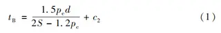
(1) Minimum Wall Thickness of the Flow Passage
The wall thickness of the valve passage is determined by:
where:
P — Pressure rating index, 4500 psi (≈31.03 MPa)
d — Minimum flow passage diameter, 43 mm
S — Allowable stress, 7000 MPa
C — Corrosion allowance, 2.5 mm
The calculated minimum wall thickness at the valve passage is 36.25 mm.
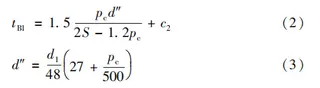
(2) Minimum Wall Thickness of the Valve Cavity
The wall thickness of the valve cavity is calculated using:
where:
d″ — diameter used for determining the neck wall thickness, mm
d₁ — maximum internal diameter of the neck, taken as 73 mm
The minimum wall thickness of the valve cavity is calculated to be 45.5 mm. Using these calculations and by referencing the design of conventional fixed ball valves, the valve body model was developed. The minimum wall thickness of the flow passage is 37.9 mm, while the minimum wall thickness of the valve cavity is 48.6 mm, as illustrated in Figure 1.
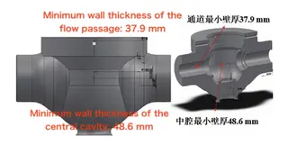
Figure 1 Schematic Diagram of the Ball Valve Body Model
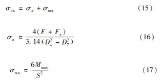
The valve body and bonnet are joined using a self-tightening sealing structure. The connection between the bonnet and valve body features a self-energizing seal reinforced with restraining bolts and rings, as illustrated in Figure 2. The restraining ring is secured to the bonnet using restraining bolts that apply a defined preload. Simultaneously, the quad-ring is anchored to the valve body with tension bolts, and a pressure pad is employed to restrict any upward movement. During operation, the internal fluid exerts an upward force on the bonnet. This force increases the contact pressure between the bonnet and the pressure pad, enhancing the seal through the self-energizing effect of the medium pressure. The bonnet assembly’s strength is analyzed in accordance with GB/T 150–2024 “Pressure Vessels.” The structure and dimensions of the restraining ring are shown in Figure 3. The restraining ring is made of 12Cr2Mo1 steel, with an allowable stress of 187 MPa at 100 °C.
(1) Bending Stress of the Circumferential Section a–a
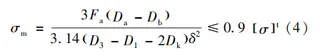
where:
F — Preload of restraining bolt, 72,166 N
Do — Outer and inner diameters of the section (mm)
δ — Section thickness, 22.25 mm
σt— Allowable stress, 187 MPa
The calculated bending stress of the restraining ring’s longitudinal section is 112.1 MPa, which is below the allowable limit of 0.9 × 187 MPa = 168.3 MPa.
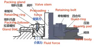
Figure 2 Sealing principle of the valve body and bonnet
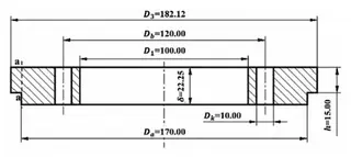
Figure 3 Structural schematic of the restraining ring
(2) Equivalent Stress of Circumferential Section a–a
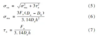
where:
σma — Bending stress of section a–a, MPa
τa— Shear stress of section a–a, MPa
The calculated bending stress of the restraining ring’s longitudinal section is 112.1 MPa, which is below the allowable limit of 0.9 × 187 MPa = 168.3 MPa. The structure and dimensions of the quad-ring are illustrated in Figure 4. The quad-ring is made of 12Cr2Mo1, with an allowable stress of 187 MPa at 100 °C.
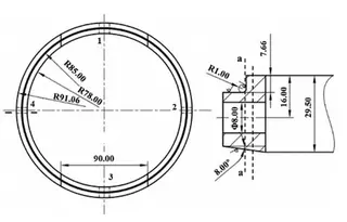
Figure 4 Structural schematic of the quad-ring
The a–a circumferential section of the quad-ring lies on the same annular surface as that of the restraining ring. The shear stress in this section is calculated using the following formula:
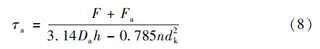
The calculated shear stress on the a–a section of the quad-ring is 133.48 MPa, which is below the allowable limit of 168.3 MPa, confirming that the quad-ring maintains structural safety.
(3) Restraining Bolt Design
The restraining bolts are made of 35CrMoA, with an allowable stress of 190 MPa at 100 °C. The required diameter of the bolt shank is determined as:
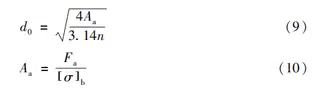
where:
Aa— Minimum required cross-sectional area (mm²)
n — Number of bolts, 4
Here, σb— allowable stress of the bolt material, 190 MPa.
The calculated bolt diameter is 7.78 mm; therefore, a standard M8 restraining bolt is selected.
4. Bonnet Structural Analysis
The structure and dimensions of the bonnet (top cover) are shown in Figure 5. The material selected is F53 stainless steel, which has a yield strength of 550 MPa and an allowable stress of 296 MPa at 100 °C.
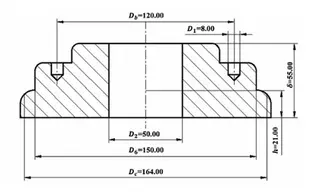
Figure 5 Structural schematic of the bonnet
The bending stress of the longitudinal section is determined by:
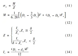
where:
M — Bending moment, N·mm
Z — Section modulus, mm³
Ic — Moment of inertia, mm⁴
The calculated bending stress is 192.4 MPa, which is below the allowable limit of 0.7 × 296 MPa = 207.2 MPa.
(5) Cylinder End Analysis
The end section of the cylinder is shown in Figure 6. The material used is F53, with an allowable stress of 296 MPa at 100 °C.
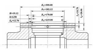
Figure 6 Structural schematic of the cylinder end
The a–a circumferential section at the cylinder end lies on the same annular surface as the restraining ring and quad-ring. The equivalent stress for this section is calculated as follows:
The equivalent stress of the a–a section at the cylinder end is 69.52 MPa, which is well below the allowable limit of 0.9 × 296 MPa = 266.4 MPa. After completing the above calculations, the assembled structure of the valve body and bonnet is illustrated in Figure 7.
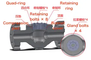
Figure 7 3D model of the valve body and bonnet assembly
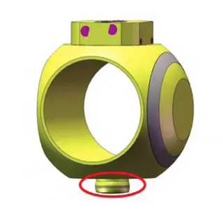
2.2 Spherical Structure Design
The valve core features a hemispherical design. This configuration reduces the ball’s weight and lowers the rotational torque while simultaneously increasing the pressure-bearing area on the inner side of the ball during closure. Consequently, the ball experiences slight deformation in the closing direction, which improves the sealing performance. One side of the ball features a flat opening, while the opposite side has a V-shaped opening, enabling flow regulation when needed. Rounded edges are incorporated to protect the sealing ring from damage during operation. The upper portion of the ball, connecting to the valve stem, incorporates a square groove to enable efficient torque transfer from the stem to the ball. The lower portion, which interfaces with the valve seat, features a circular protrusion to accommodate bearing installation, thereby reducing frictional torque during rotation. The 3D model and key dimensions of the hemispherical valve core are presented in Figure 8.
Figure 8 Schematic diagram of the ball structure
2.3 Sealing Structure Design
Since the working pressure reaches 45 MPa, conventional bolt-and-nut connections cannot ensure a reliable joint between the valve body and the bonnet. Therefore, a pressure-activated self-tightening seal is used at the end of the valve body. Because the valve core is hemispherical, a one-way sealing arrangement is used, with the sealing assembly installed solely on the downstream side, as illustrated in Figure 9. The valve seat and ball core employ a self-energizing sealing structure supported by a disc spring. When the valve is closed, the medium pressure on the inner side of the ball compresses the valve seat. This compressive force is transmitted to the disc spring positioned behind the support ring, causing the spring to deform and produce a reactive force. This reactive force drives the valve seat toward the ball, pressing it firmly against the sealing surface and thereby improving the sealing performance.
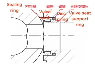
Figure 9 Schematic diagram of the sealing assembly structure
2.4 Material Selection
Based on ASME B16.34 “Flanged, Threaded, and Welding End Valves” and ASTM A182/A182M–2015 “Forged or Rolled Alloy Steel and Stainless Steel Flanges, Forged Fittings, Valves, and Components for High-Temperature Service,” the valve body, ball, and other primary pressure-bearing components were fabricated from F53 stainless steel. In compliance with ASME B16.34 “Flanged, Threaded, and Welded End Valves” and ASTM A182/A182M–2015 “Forged or Rolled Alloy Steel and Stainless Steel Flanges, Forged Fittings, Valves, and Components for High-Temperature Service,” the valve body, ball, and other primary pressure-bearing components are manufactured from F53 stainless steel. F53 stainless steel has high chromium and molybdenum content, which provides excellent resistance to pitting, crevice, and uniform corrosion. Its duplex microstructure delivers superior resistance to stress corrosion cracking while retaining high mechanical strength. The key physical and mechanical properties of F53 are summarized in Table 2.
Table 2 F53 Material Properties
|
Property |
Value |
|
Density at 20 °C (kg/m³) |
7800 |
|
Tensile strength (MPa) |
795 |
|
Yield strength (MPa) |
550 |
3. Stress Simulation Analysis
Strength and sealing performance are critical indicators of high-pressure valves. Therefore, a static analysis of the valve body is conducted to evaluate the stress distribution of the structure under high-pressure conditions. Finite element simulation is employed to identify the regions most affected by internal pressure, providing a basis for targeted structural reinforcement in subsequent design optimization. At the same time, the specific contact pressure at the sealing interface is calculated to evaluate the sealing performance. According to GB/T 4732–2024, Steel Pressure Vessels — Analysis and Design Standard, the principles for selecting the linear stress path are as follows:
The linearization path should be defined along the shortest distance through the wall thickness at the location of the maximum stress intensity.
For regions with relatively high stress, the linearization path should be established along the wall thickness direction to capture the stress distribution across the section.
3.1 Valve Body Stress Analysis
The valve body is made of F53 stainless steel, which has a yield strength of Rel = 550 MPa and an allowable stress of [σ] = 296 MPa at 100 °C. In the numerical simulation, a 10 kg actuator is modeled as a mass point positioned 50 mm directly above the center of the valve. An internal pressure of 45 MPa is applied, and fixed boundary conditions are imposed at both pipe connection ends. The overall von Mises stress distribution of the valve body is subsequently determined.As shown in Figure 10, the maximum stress is concentrated in the sharp-corner regions and thin-wall sections of the valve seat flow channel, as well as in the bottom groove used for ball positioning. Linearization is performed along the wall thickness direction at these maximum stress locations and other critical sections. The stress evaluation results are summarized in Table 3, showing that the valve body satisfies the strength criteria and successfully passes verification.
3.2 Ball Stress Analysis
The ball is fabricated from F53 stainless steel. Fixed constraints are applied at the upper and lower contact surfaces where the ball interfaces with the valve stem and valve body. An internal pressure of 45 MPa is applied to the inner surface of the ball, and the overall von Mises stress distribution is determined using finite element analysis. As shown in Figure 11, the maximum stress is concentrated at the sharp corners of the flat opening. Linearization is carried out along the wall thickness at the locations of peak stress and other critical high-stress areas. The stress assessment results, summarized in Table 4, indicate that the ball satisfies the design strength criteria and successfully passes verification.
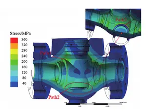
Figure 10 Stress contour and linearization path of valve body
Table 3 Stress evaluation of valve body
|
Path |
Stress intensity and combined stress intensity |
Calculated stress intensity / MPa |
Allowable stress intensity limit / MPa |
Evaluation conclusion |
|
1. Local membrane stress intensity Sₘ |
93.34 |
1.5 Sₘ = 1.5 × 296 = 444 |
Pass |
|
|
1. Primary + secondary stress intensity S₁v |
153.84 |
3 Sₘ = 3 × 296 = 888 |
Pass |
|
|
2. Local membrane stress intensity Sₙ |
44.12 |
1.5 Sₘ = 1.5 × 296 = 444 |
Pass |
|
|
2. Primary + secondary stress intensity S₁v |
108.7 |
3 Sₘ = 3 × 296 = 888 |
Pass |
|
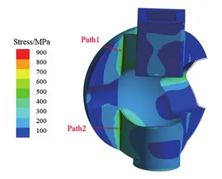
Figure 11 Stress contour and linearization path of ball
3.3 Simulation Analysis of End Sealing Assembly
The valve seat is made of F53 stainless steel, while the sealing ring is constructed from nitrided steel with a cobalt-based hard alloy weld overlay. The allowable sealing pressure is 300 MPa, and the sealing surface width is 7.45 mm. Accordingly, the required sealing pressure is calculated as:
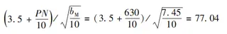
The average sealing pressure is calculated circumferentially for each 5° sector and axially for each 0.01 mm-wide ring. The results, presented in Figure 12, show that the circumferential sealing pressure is evenly distributed, with an average value of 298 MPa. The maximum axial stress is concentrated at both ends of the sealing surface, reaching its peak at the bottom and gradually decreasing upward to an average of 251 MPa. All values remain within the required and allowable sealing pressure limits, confirming that the valve achieves reliable sealing performance. Table 4 summarizes the stress evaluation of the ball, showing that all calculated stresses are below the allowable limits, and the ball meets the required strength criteria.
Table 4 Stress Evaluation of the Ball
|
Path |
Stress Intensity and Combined Stress Intensity |
Calculated Stress Intensity / MPa |
Allowable Stress Intensity Limit / MPa |
Evaluation Conclusion |
|
1. Local membrane stress intensity Sₙ |
197.37 |
1.5 Sₘ = 1.5 × 296 = 444 |
Pass |
|
|
1. Primary + secondary stress intensity Sᵢv |
333.77 |
3 Sₘ = 3 × 296 = 888 |
Pass |
|
|
2. Local membrane stress intensity Sₕ |
191.98 |
1.5 Sₘ = 1.5 × 296 = 444 |
Pass |
|
|
2. Primary + secondary stress intensity Sᵢv |
343.35 |
3 Sₘ = 3 × 296 = 888 |
Pass |
|
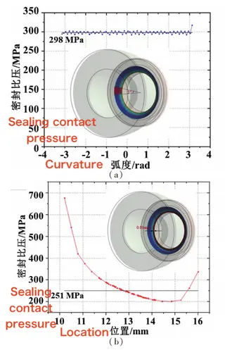
Figure 12 Circumferential and Axial Sealing Pressure Distribution
(a) Circumferential sealing pressure (b) Axial sealing pressure
4. Conclusion
This paper presents the structural design of a high-pressure ball valve in accordance with relevant standards, including the dimensional design and material selection for key components such as the valve body, bonnet, ball, and sealing assembly. The design guarantees the valve’s structural integrity, sealing performance, and operational safety under a working pressure of 45 MPa. Finite element simulations were used to perform static stress analyses on each component, revealing the stress distribution and sealing pressure characteristics. The results indicate that the maximum stresses in both the valve body and the ball remain below the allowable limits of the materials, confirming sufficient structural strength. The end sealing assembly exhibits a uniformly distributed sealing pressure within an acceptable range, ensuring excellent sealing performance and effectively preventing fluid leakage. Overall, this study provides a scientific foundation for the design and manufacture of high-pressure ball valves, offering technical guidance for further optimization and serving as a valuable reference for valve manufacturers and industrial users.
Send your message to this supplier
Related Articles from the Supplier

High-pressure Angle Globe Valves in ASTM A182 F22
- Dec 17, 2021
High-pressure Aluminum Bronze Valves for Sea Water
- Feb 13, 2023
High Pressure Globe Valve PN320, Forged Material
- Apr 13, 2026
Extra High Pressure Y-type Globe Valves
- Nov 16, 2021
Related Articles from China Manufacturers
Related Products Mentioned in the Article
Baltic Valve Co., Ltd.
- https://www.baltic-valve.com/
- Business Type: Trading, Industry & Trading, Manufacturer,
Supplier Website
Source: https://www.baltic-valve.com/high-pressure-ball-valve-design-strength-and-sealing-analysis.html