Application of Magnetic Flux Leakage (MFL) Inspection Technology for Subsea Pipeline Valves
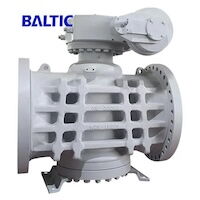
Subsea pipelines are critical links between offshore oil and gas production facilities and onshore terminals, transporting media such as crude oil and natural gas. Their safe and reliable operation is essential for maintaining normal oilfield production and protecting the marine ecological environment. Within subsea pipeline systems, variable-diameter ball valves are key control components, responsible for functions such as flow regulation and medium isolation. However, due to prolonged exposure to complex marine environments, these valves are susceptible to corrosion, wear, and other degradation mechanisms, which may lead to various defects. If such defects are not detected and mitigated in a timely manner, valve failure may occur, potentially resulting in leakage incidents that cause significant economic losses and environmental pollution. Magnetic flux leakage (MFL) internal inspection technology is an effective non-destructive testing method. When applied to the inspection of variable-diameter ball valves in subsea pipelines, this technology enables accurate detection and evaluation of internal defects in pipelines and valves without causing structural damage. It allows potential defects within ball valves to be identified at an early stage, thereby providing a reliable basis for maintenance planning and valve replacement decisions.
1. Principle and Characteristics of Magnetic Flux Leakage Internal Inspection Technology
1.1 Principle of Magnetic Flux Leakage Internal Inspection Technology
Magnetic flux leakage internal inspection technology is based on the magnetic properties of ferromagnetic materials. During inspection, when a ferromagnetic component is magnetized and defects such as cracks or corrosion pits are present on or near its surface, the local magnetic permeability at the defect location changes, causing distortion of the magnetic field lines. As a result, part of the magnetic flux leaks out of the material’s surface, forming a leakage magnetic field.
By measuring the intensity and spatial distribution of this leakage magnetic field, the location, size, and morphology of the defect can be determined and evaluated. In the internal MFL inspection of variable-diameter ball valves used in subsea oilfield pipelines, key components such as the valve ball and seat are typically made of ferromagnetic materials. The inspection process therefore begins by magnetizing the ball valve to near saturation using a dedicated magnetization device. Magnetic sensors, such as Hall-effect sensors or fluxgate sensors, are then used to detect leakage magnetic field signals on the surface of the ball valve. After signal amplification and filtering, the measured data are transmitted to a data acquisition system for processing and analysis, where defect characteristics are extracted. In addition, a mileage wheel is used to record the distance traveled by the inspection tool inside the pipeline, enabling accurate determination of defect locations.
1.2 Characteristics of Internal Magnetic Flux Leakage Detection Technology
Internal magnetic flux leakage (MFL) detection technology offers several key advantages. First, it is a non-contact inspection method. During testing, inspectors are not required to make direct contact with the object under inspection, thereby avoiding any potential mechanical damage to pipelines or valves. For this reason, the technology is widely used for the inspection of in-service pipelines and valves. In addition, MFL inspection is highly efficient, enabling rapid and continuous testing at speeds of several kilometers per hour. It can detect a wide range of defect types, including cracks, corrosion pits, and slag inclusions in pipelines and valves. The inspection results are intuitive and easy to interpret: through data processing and analysis, defect information can be clearly visualized, providing technicians with a reliable basis for defect identification and evaluation. Moreover, the technology demonstrates strong adaptability and can be used for pipelines and valves of various diameters, materials, and operating conditions.
2. Application of Internal Magnetic Flux Leakage Technology in the Inspection of Reducing Ball Valves in Subsea Oilfield Pipelines
2.1 Pre-Inspection Preparation
Prior to applying internal magnetic flux leakage (MFL) detection technology to inspect reducing ball valves in subsea oilfield pipelines, comprehensive pre-inspection preparations are required to ensure the smooth and reliable execution of the inspection. The main preparatory tasks are as follows. First, inspection personnel shall systematically collect all relevant technical and operational information for the reducing ball valves to be inspected. This includes, but is not limited to, the valve model and specifications, material grade, operating history, installation location, and maintenance records. Second, the pipeline must be thoroughly cleaned in strict accordance with cleanliness standards. Mechanical steel brushes and magnetic cleaning tools are used sequentially to remove oil deposits, debris, and other contaminants from the inner wall of the pipeline. This ensures that no solid impurities remain inside the pipeline and that the conditions meet the requirements for internal inspection. After cleaning, the internal diameter is checked to identify any potential reductions. A caliper disc is used to measure the actual internal diameter of the pipeline, and the measured values are compared with the internal diameter of the reducing ball valve specified in the pipeline accessory drawings. This allows any diameter changes to be identified and provides accurate internal diameter data. In addition, a site survey of the subsea pipeline and the reducing ball valve locations is conducted to assess seabed topography, geomorphological conditions, water flow characteristics, and other environmental factors. Based on this comprehensive risk assessment, inspection personnel can select an appropriate MFL detector according to the valve diameter and actual inspection conditions. Prior to deployment, the detector must be fully debugged and calibrated to ensure its performance meets the inspection requirements. Following the completion of the above investigations and preparations, a detailed inspection plan is developed. The plan specifies the inspection schedule, route, personnel deployment, safety measures, and operational procedures, ensuring that each stage of the inspection is properly coordinated and that adequate preparations are in place for on-site execution.
2.2 Inspection Operation Implementation
During inspection execution, after the inspection route is confirmed, the calibrated MFL detector is launched into the subsea pipeline using a dedicated launching device. Once inside the pipeline, the detector travels along the pipeline axis at a constant speed, propelled by the conveyed medium, while performing inspection of the reducing ball valve during steady movement. During operation, the magnetization unit within the detector magnetizes the inspected section of the pipeline to near saturation. Magnetic sensors continuously capture magnetic flux leakage signals generated by defects, which are converted into electrical signals and transmitted wirelessly to the data processing system for storage and analysis. Meanwhile, a mileage wheel records the distance traveled by the detector within the pipeline, providing precise positional information for defect localization.
2.3 Inspection Data Analysis and Evaluation
After completing the inspection, personnel process and analyze the data stored in the data processing system to accurately interpret the results and determine the actual operating condition of the reducing ball valve. Since the raw data are inevitably affected by noise, environmental interference, and equipment-related errors, systematic preprocessing and intelligent analysis are required to enhance the reliability and accuracy of the evaluation results.
During the data preprocessing stage, operations such as filtering and noise reduction, signal normalization, and multi-channel alignment are performed to improve data quality. During filtering and denoising, a low-pass filter is applied at the data acquisition stage to suppress high-frequency electromagnetic interference, while a band-pass filter is used to retain the characteristic frequency band of magnetic flux leakage signals, typically ranging from 100 Hz to 10 kHz. An adaptive wavelet thresholding algorithm dynamically adjusts thresholds based on local signal characteristics, effectively removing impulsive noise. For periodic interference sources, such as pipeline vibrations, independent component analysis (ICA) is employed to separate and remove noise components. During signal normalization, sensor signals are scaled to the [0, 1] range to eliminate differences in sensor sensitivity.
In addition, a cross-correlation algorithm is applied to align multi-channel signals, compensate for sensor position deviations, and ensure consistency of defect features across both spatial and temporal dimensions. Following data preprocessing, appropriate defect identification algorithms are applied to analyze the processed data and detect internal defects in the reducing ball valve. A one-dimensional convolutional neural network (1D-CNN) is constructed, with the preprocessed magnetic flux leakage signals used as inputs to automatically extract time–frequency features associated with defects. Transfer learning techniques, such as employing a pre-trained ResNet-18 model, are used to accelerate model convergence and improve defect identification accuracy. Based on the extracted features, key defect parameters are determined, including defect length (calculated from the signal peak width), defect width (estimated using the half-width at half-maximum, FWHM), and defect depth. Defect depth is estimated by analyzing changes in the magnetic field gradient, using calibration curves established through finite element simulations. Based on the extracted defect feature data, statistical indicators such as the root mean square (RMS) and crest factor (CF) of the magnetic flux leakage signal are calculated. As defect severity increases, both RMS and CF values rise correspondingly, enabling quantitative assessment of defect severity and classification of defect levels. Finally, the inspection personnel prepare a comprehensive inspection report. The report includes inspection results—such as magnetic flux leakage signal intensity distribution cloud maps generated using MATLAB or ParaView to visually illustrate defect location and morphology—defect distribution maps showing defect coordinates on an axially unfolded pipeline diagram with color gradients indicating severity, defect assessment conclusions, and corresponding maintenance and repair recommendations.
3. Case Study of Magnetic Flux Leakage Inspection of Reducing Ball Valves
3.1 Project Background
As part of routine maintenance, a mixed-transport subsea pipeline in Phase II of an oilfield in the Bohai Sea was inspected to comprehensively assess pipeline integrity and the operating condition of the reducing ball valves. The pipeline has an outer diameter of 320 mm, an inner diameter of 300 mm, a wall thickness of 10 mm, and a total length of 2,634 m, and is equipped with multiple reducing ball valves. Internal magnetic flux leakage (MFL) inspection technology was applied to accurately assess the overall condition of the reducing ball valves, detect potential defects at an early stage, and implement appropriate mitigation measures. The objective was to ensure the safe, stable, and reliable operation of the subsea pipeline system.
3.2 Inspection Process Design
3.2.1 Pre-Inspection Preparation
Before conducting magnetic flux leakage inspection of the reducing ball valves, inspection personnel collected comprehensive technical and operational data for the valves installed along this section of the pipeline. Pipeline cleaning operations were then carried out to remove internal impurities and accumulated water, ensuring the inspection tool could pass through the pipeline unobstructed. Based on the original design dimensions, appropriate caliper discs were selected to accurately measure the internal diameters of the pipeline and the reducing ball valves. The inspection results indicated that the minimum caliper disc deformation diameter was 293 mm in straight pipe sections and 246 mm in elbow sections. The latest caliper measurements were fitted and compared with the pipeline accessory drawings, revealing slight deviations from the nominal internal diameters of the reducing ball valves. To minimize the impact of residual deposits and ensure inspection accuracy, additional high-throughput cleaning operations were performed. Based on the pipeline specifications and ball valve parameters, an appropriate magnetic flux leakage detector was selected. Furthermore, the detector was modified and optimized according to the actual inspection requirements of the variable-diameter ball valves, enhancing its adaptability and data acquisition accuracy. During inspection, the reducing ball valves were operated to either the fully open or fully closed position to facilitate a stable and effective internal inspection.
Table 1. Analysis of Inspection Results for Reducing Ball Valves
|
Ball Valve No. |
Defect Location |
Defect Type |
Peak MFL Signal (mV) |
Defect Depth (mm) |
|
1 |
Valve body center |
Corrosion |
150 |
3.0 |
|
1 |
Near valve seat |
Crack |
200 |
4.0 |
|
2 |
Valve stem sealing area |
Wear |
100 |
2.0 |
|
3 |
Ball surface |
Pitting |
80 |
1.6 |
Based on the pipeline specifications and the structural parameters of the reducing ball valves, inspection personnel selected a suitable model of magnetic flux leakage (MFL) detector. To meet the specific requirements of internal inspection for variable-diameter ball valves, the detector was further optimized and adapted to improve its compatibility with diameter transitions and enhance data acquisition accuracy. During the inspection process, the reducing ball valves were operated to either the fully open or fully closed position, ensuring stable internal conditions and consistent signal collection. The inspection results demonstrate that the MFL technique can effectively identify the location, type, and severity of defects in reducing ball valves, providing a reliable basis for subsequent condition assessment and maintenance decisions.
3.2.2 Inspection Operation Implementation
During inspection, the calibrated magnetic flux leakage detector (MFLD) was deployed into the subsea pipeline using a dedicated launching device. Driven by the flow medium, the MFLD traveled along the pipeline axis at a constant speed, continuously inspecting the reducing ball valves during steady motion. Throughout the inspection, the sensor array integrated into the MFLD continuously collected magnetic flux leakage signals from the surfaces of the reducing ball valves in real time. The acquired signals were transmitted to the data acquisition system, where they were recorded and stored according to the predefined sampling frequency and number of data points. This ensured that the collected data accurately captured the defect-related magnetic flux leakage characteristics of the ball valves, providing a reliable basis for subsequent data analysis and evaluation.
3.2.3 Data Analysis and Processing
Upon completion of the internal inspection, the data acquired by the Magnetic Flux Leakage Detector (MFLD) were forwarded to the data analysis and processing system. Professional data analysis software was then used to process and interpret the collected signals. The characteristic features of the magnetic flux leakage signals were extracted and analyzed, allowing for the precise identification of defects in the reducing ball valves—including their type, location, and dimensions. First, the raw signals were filtered and denoised to suppress noise and interference, enabling the subsequent extraction of magnetic flux leakage signal features. Following this, characteristic parameters reflecting defect severity and spatial distribution—including but not limited to signal peak amplitude and waveform width—were subsequently derived from the processed signals.
Following parameter extraction, a quantitative analysis of the defects was conducted. This analysis was based on the established correlation within MFL principles between defect dimensions and magnetic flux leakage signal intensity. Experimental calibration and theoretical analysis yielded the following quantitative relationship between defect depth and the peak magnetic flux leakage signal:
d=k×Vp
where d signifies the defect depth (mm); Vp indicates the peak magnetic flux leakage signal value (mV); and k is the proportionality coefficient, incorporating factors such as the material properties and magnetization state of the ball valve. In this study, the coefficient k was determined via calibration experiments and relevant calculations, and was thus fixed at 0.02.
Magnetic flux leakage inspection detected defects of varying severity in three reducing ball valves, as summarized in Table 1. Specifically, Ball Valve No. 1 was found to have sustained corrosion at the valve body center and cracking near the valve seat, with estimated defect depths of 3.0 mm and 4.0 mm, respectively. Subsequent inspection revealed the following: Ball Valve No. 2 had wear at the stem sealing area (depth: 2.0 mm), while Ball Valve No. 3 presented pitting on the ball surface (depth: 1.6 mm).
3.3 Evaluation of Inspection Results
The inspection results were systematically analyzed and assessed in strict accordance with applicable standards and specifications, including GB/T 26640—2011 for minimum valve body wall thickness and API 570 (Fifth Edition) for in-service piping system inspection, evaluation, repair, and modification. In accordance with these standards, defects such as corrosion or wear require repair or replacement when their depth exceeds 10% of the ball valve’s nominal wall thickness. For crack-type defects, corrective action is required regardless of depth due to the high risk of propagation. In this case, Ball Valve No. 1 exhibited a crack with a depth of 4.0 mm, exceeding 10% of the assumed wall thickness of 30 mm; therefore, the valve requires repair or replacement. The corrosion depth at the center of Ball Valve No. 1’s body was 3.0 mm, which does not exceed the 10% threshold. However, due to its location and potential for further progression, enhanced monitoring and follow-up inspections are recommended. The wear depth at the valve stem sealing area of Ball Valve No. 2 was 2.0 mm, also below the 10% limit, allowing continued operation under standard inspection intervals. The pitting depth observed on the ball surface of Ball Valve No. 3 was 1.6 mm, which remains within acceptable limits and does not compromise continued service at this stage. Overall, the evaluation indicates that while most detected defects remain within allowable limits, critical cracks require immediate corrective action to ensure operational safety.
4. Conclusion
This study examined the application of internal magnetic flux leakage (MFL) inspection technology for reducing ball valves in subsea oilfield pipelines through a practical engineering case. The results demonstrate that magnetic flux leakage (MFL) inspection can effectively and accurately detect internal defects in reducing ball valves—including corrosion, wear, cracks, and pitting—while providing quantitative information on defect location and severity. The application of this technology provides a reliable technical basis for maintenance personnel to make informed decisions on inspection, repair, and replacement. Consequently, internal magnetic flux leakage (MFL) inspection technology plays a crucial role in ensuring the safe, stable, and reliable operation of reducing ball valves in subsea oilfield pipeline systems.
Send your message to this supplier
Related Articles from the Supplier


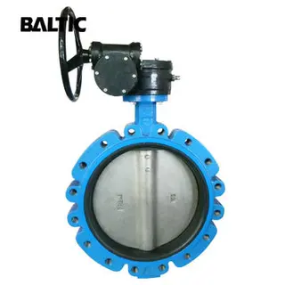
The Selection and Application of Butterfly Valves
- Oct 15, 2020

Application Prospect of Stainless Steel Valves
- Aug 03, 2020
Related Articles from China Manufacturers

Application of Industrial Manipulator
- Jun 10, 2020
Application of PLC in Automatic Manipulators
- Sep 27, 2022

Application of Robots in Automatic Packaging
- Sep 29, 2022

Application of Forging Components
- Nov 11, 2014

Application Of Fixed Tube Sheet Heat Exchangers
- Sep 19, 2017
Application of Welded Pipe
- Apr 20, 2016
Application of Flanges in Mechanical Design
- Mar 30, 2015
Application of UG Software in Injection Mold
- Jul 11, 2016
Related Products Mentioned in the Article
Baltic Valve Co., Ltd.
- https://www.baltic-valve.com/
- Business Type: Trading, Industry & Trading, Manufacturer,
Supplier Website
Source: https://www.baltic-valve.com/application-of-magnetic-flux-leakage-mfl-inspection-technology-for-subsea-pipeline-valves.html