All-Welded Ball Valve Body Design Comparison: Strength, Durability, and Performance
The valve body of the all-welded ball valve is connected by welding and features few external leakage points, high strength, and a compact structure. It is widely used in industries such as oil, natural gas, and chemicals. Currently, various valve body structures are available. Common all-welded ball valve body structures include cylindrical, conical, and spherical types, each with its own unique characteristics. By comparing and analyzing the characteristics of the valve body blank, minimum wall thickness, finite element analysis, welding characteristics, and the impact of the production and manufacturing process, it is concluded that the cylindrical valve body offers design flexibility and versatility, but attention must be paid to its strength and deformation control. The conical valve body performs better in terms of cost and welding deformation control, while the spherical valve body offers clear advantages in wall thickness and weight, though attention must be given to strength and welding process challenges. This article provides an in-depth analysis of the characteristics of three common valve body structures, aiming to offer a reference for the design and manufacture of all-welded ball valve bodies. It also considers the actual conditions of the factory to select the most suitable valve body structure for design and production.
1. Overview
Ball valves are renowned for their low flow resistance and excellent sealing performance, which makes them widely used in the petroleum, natural gas, and chemical industries. The all-welded ball valve is a specially designed variant where the valve body is fabricated by welding, eliminating the need for bolted connections and resulting in a more compact structure. This design offers several advantages, including high strength, fewer external leakage points, excellent sealing performance, and a long service life. It is especially suitable for field installations, stations, buried pipelines, long-distance transmission lines, and similar applications. Many manufacturers currently produce all-welded ball valves, but their structural designs—especially the valve body structures—vary between manufacturers. Common valve body structures include cylindrical, conical, and spherical types. As the main pressure-bearing component, the valve body plays a critical role in ensuring the safety of both the valve and the pipeline. Therefore, selecting the appropriate valve body structure is a key consideration in the design and manufacturing process. By analyzing the structural characteristics of various all-welded ball valve bodies, manufacturers can better align product designs with their actual production conditions. This facilitates the development of stable, reliable, and cost-effective all-welded ball valves, thereby enhancing market competitiveness.
2. Valve Body Structures
The valve body of a all-welded ball valve typically consists of a main body and side bodies. The common external structures of all-welded ball valve bodies are shown in Figure 1. The cylindrical valve body structure is widely used and mainly consists of a cylindrical main body and two cylindrical side bodies, which are joined by welds 1 and 2, as shown in Figure 1(a). The conical valve body structure is based on the cylindrical design, featuring a shorter main body and longer side bodies. It primarily consists of a cylindrical main body and two conical side bodies, joined by welds 1 and 2, as shown in Figure 1(b). The spherical valve body structure mainly consists of two valve bodies, left and right. The valve cavity is spherical, with cylindrical transitions at both ends, which are joined by weld 1, as shown in Figure 1(c).
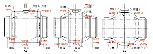
(a) Cylindrical valve body (b) Conical valve body
Figure 1: Common Valve Body Structures
3. Analysis of Valve Body Structure Characteristics
3.1 Analysis of Blank Characteristics
However, free-forged blanks have large machining allowances, which increase raw material consumption and processing costs. To control material expenses, the valve body length can be maximized while minimizing the length of the side sections, thereby reducing both material usage and machining costs. For conical valve bodies, the side sections can be produced by either free forging or die forging. However, because free forging often leads to large machining allowances and higher production costs, die forging is usually preferred to better control expenses. Die forging significantly reduces raw material waste and machining effort, although it requires high mold costs. This method is well-suited for mass production or when forging dies are already available. The valve cavity of a spherical valve body has a spherical shape, and its blank is typically produced by die forging. Die-forged spherical valve bodies require minimal machining allowances and tend to be relatively lightweight. However, as with other die-forged components, the high cost of forging dies makes this method most suitable for mass production or when existing dies can be reused.
3.2 Minimum Calculated Wall Thickness of the Valve Body
The valve body of a all-welded ball valve typically comprises a main body and two side sections. Common external structures of all-welded ball valve bodies are illustrated in Figure 1. The widely used cylindrical valve body structure primarily consists of a cylindrical main body and two simple side sections, joined by welds 1 and 2, as shown in Figure 1(a). The conical valve body structure builds upon the simple design by shortening the main body and extending the side sections. It consists of a basic central body and two conical side bodies, joined by welds 1 and 2, as shown in Figure 1(b). The spherical valve body structure primarily consists of two symmetrical side bodies. It features a spherical valve cavity with cylindrical ends, which are joined by weld 1, as shown in Figure 1(c). According to ASME VII-1 Pressure Vessel Construction Rules UG-27, the minimum wall thickness of an internal pressure shell is calculated as follows:
The minimum wall thickness for cylindrical and conical valve bodies is calculated using the following formula:

The minimum wall thickness for spherical valve bodies is calculated using the following formula:

Where:
t — minimum wall thickness of the valve body (mm)
P — design pressure (MPa)
R — inner radius of the valve body (mm)
S — allowable stress of the material at operating temperature (MPa)
E — weld joint efficiency factor
By comparing formulas (1) and (2), it is evident that, under the same size, pressure, material, and weld joint efficiency, the spherical valve body has the smallest minimum calculated wall thickness.
3.3 Valve Body Strength Analysis
Using the valve body of an NPS10 Class 150 all-welded ball valve as an example, the minimum wall thickness was calculated based on formulas (1) and (2). SolidWorks software was used to create 3D models of the welded cylindrical, conical, and spherical valve bodies, with simplifications applied to preserve their main features and structural characteristics. The simplified valve body models are shown in Figure 2. All valve bodies were assigned the same material, with the material properties detailed in Table 1.
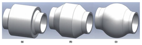
(a) Cylinder valve body (b) Conical valve body (c) Spherical valve body
Figure 2 Simplified valve body models
Table 1 Valve Body Material Parameters
|
Parameter |
Value |
|
Tensile Strength (MPa) |
485 |
|
Yield Strength (MPa) |
250 |
|
Poisson’s Ratio |
0.29 |
|
Elastic Modulus (GPa) |
205 |
|
Density (kg/m³) |
7850 |
The same boundary conditions were applied to each valve body model. An internal pressure of 3 MPa was uniformly distributed perpendicular to the inner surface of the valve body, as shown by the red arrows in Figure 3. The valve body was fixed to the pipeline by constraining the end faces at both ends to prevent longitudinal displacement. Additionally, the straight sections at both ends were restrained to restrict both longitudinal displacement and rotation, as indicated by the green arrows in Figure 3. Identical mesh parameters were applied to all valve body models using a solid mesh with the standard mesher. The Jacobian quality was set to 4 points, the cell size to 10 mm, and the tolerance to 0.5. The mesh division results are shown in Figure 4.
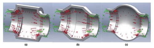
Figure 3. Schematic diagram of boundary conditions
(a) cylindrical valve body (b) conical valve body (c) spherical valve body
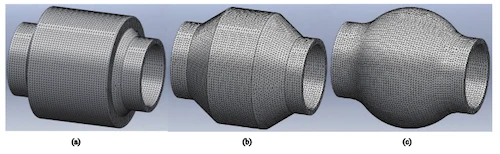
Figure 4. Schematic diagram of mesh division
(a) cylindrical valve body (b) conical valve body (c) spherical valve body
Finite element analysis of the three valve body structures was performed using SolidWorks Simulation software. The resulting deformation patterns are shown in Figure 5. Between the cylindrical and conical valve bodies, the cylindrical valve body is longer and maintains a cylindrical shape. Under internal pressure, its greater length creates a longer moment arm, leading to higher bending stress at the center of the valve body. Figures 5(a) and 5(b) show that the maximum deformation occurs at the center of both the cylindrical and conical valve bodies, with the cylindrical valve body exhibiting greater maximum deformation than the conical valve body. For a all-welded ball valve with a cylindrical body under internal pressure, the valve neck at the midpoint of the body is more susceptible to greater deformation and stress. This increases the risk of valve stem jamming and higher operating torque, potentially affecting normal valve function. Therefore, when designing a cylindrical valve body, adequate strength and clearance must be ensured at this location to prevent deformation-induced stem jamming and torque increases. Among the cylindrical, conical, and spherical valve bodies, the spherical valve body has the thinnest wall thickness. As a result, it experiences the greatest deformation under internal pressure. Because the spherical structure is symmetrical in all directions, Figure 5(c) shows that deformation is generally uniform in the middle of the valve body, with minimal risk of stress concentration at the valve neck connection. However, the maximum deformation in the spherical valve body occurs near the valve seat, so potential sealing failure due to elastic deformation of the valve body should be taken into account during the design process.
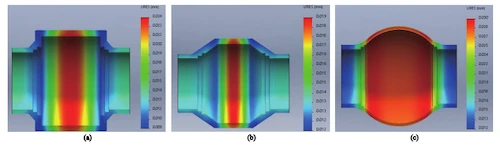
(a) Cylindrical valve body (b) Conical valve body (c) Spherical valve body
Figure 5 Schematic diagram of common valve body deformation
3.4 Welding Characteristics
The cylindrical valve body features three welds, with the main valve body weld typically located directly above the valve seat. The weld is located close to the valve seat sealing surface. During welding of the valve body and side body, significant heat is transferred to the valve seat, which can easily cause failure of the valve seat sealing ring and O-ring. Therefore, welding speed and temperature must be carefully controlled to minimize heat input. Additionally, welding can cause deformation at the valve body and valve seat sealing surfaces. This deformation can be measured after completing welding on one side of the valve body. The conical valve body also has three welds. However, because the valve body is shorter and the side sections are longer, the welds are positioned farther from the valve seat sealing surface. As a result, less heat is transferred to the valve seat during welding, reducing the risk of damage to the valve seat sealing ring and O-ring. It also minimizes deformation at the side body and valve seat sealing surfaces. Welding deformation can be measured after completing the weld on one side of the valve body. Using ASTM A350 LF2 Class 1 material as an example, the deformation measurements at the valve body and valve seat sealing positions are presented in Table 2.
Table 2 Position deformation of valve body and valve seat seal
|
Specification |
12 in |
20 in |
28 in |
36 in |
40 in |
|
Cylindrical deformation (mm) |
0.3 |
0.4 |
0.4 |
0.4 |
0.4 |
|
Conical deformation (mm) |
0 |
0 |
0 |
0 |
0 |
The spherical valve body structure has three welds, with weld 1 being the initial weld. Careful attention must be paid to accurately positioning the spherical section during welding. After welding the valve body, measuring welding deformation is challenging because of its closed structure, which also increases the risk of deformation. Therefore, weld 3 at the valve neck and weld 2 at the lower fixed axis must be opened and welded after completing the valve body welding. Creating these openings can be challenging. Additionally, welds 1 and 2, as well as welds 1 and 3, form cross welds. Strict adherence to process control parameters during welding is essential to ensure quality.
3.5 Comparative Analysis of Valve Body Weight
For valves of the same size and pressure rating, the spherical valve body has the smallest volume, while the cylindrical valve body has the largest among the cylindrical, conical, and spherical structures. In terms of weight, the spherical valve body is the lightest, followed by the conical, with the cylindrical valve body being the heaviest. As a result, the logistics costs for these three valve structures vary accordingly. For large-sized all-welded ball valves, the valve body structure greatly impacts the overall weight, which in turn affects manufacturing equipment requirements such as machining tools, lifting devices, and test benches. This is an important consideration for manufacturers.
4. Conclusion
All-welded ball valves are now widely used in the market. A detailed analysis of cylindrical, conical, and spherical valve body structures reveals the unique advantages of each and helps identify their most suitable application scenarios. The cylindrical valve body offers design flexibility but requires careful attention to strength and deformation issues; the conical valve body performs better in terms of cost efficiency and control of welding deformation. The spherical valve body offers clear advantages in wall thickness and weight but requires careful attention to strength and welding process challenges. When designing and manufacturing all-welded ball valves, it is important to comprehensively consider the valve body’s structural characteristics, material costs, manufacturing processes, and actual application requirements. The appropriate valve body structure should be chosen based on the factory’s specific conditions to ensure the valve’s stability, reliability, and cost-effectiveness. With continuous technological advancements and process optimizations, all-welded ball valves will play an increasingly vital role across diverse industries, offering more efficient and reliable fluid control solutions to support industrial development.
Send your message to this supplier
topper
- www.chinatopper.com
- Address: Xiamen
- Phone: 86-592-5819200
- Business Type: Trading, Industry & Trading, Manufacturer,
Supplier Website
Source: https://www.mfrsvalve.com/news/all-welded-ball-valve-body-design-comparison-strength-durability-and-performance.html