Failure Analysis of Heat Exchanger Tube Elbows in Thermal Power Plants
Abstract
In a thermal power plant project, small-diameter serpentine heat exchanger tubes were fabricated from 20G steel with dimensions of Ø25 × 3 mm, a bend angle of 180°, and a bend radius of 27.2 mm. The tubes were formed using a CNC top-roll tube bender. However, during the bending of one batch, severe wrinkling developed at the bend point, significantly impairing the flow characteristics of the working fluid through the elbows. This defect resulted in a scrap rate of nearly 30% and forced a complete suspension of the bending process. Analysis of the jacking force, the material’s yield strength ratio, and the macroscopic morphology identified the root causes of the failure. Since small-diameter tube elbows are critical weak points in tube bundles, such failures are relatively common. This study systematically investigates the typical failure modes of small-diameter heat exchanger tube elbows, analyzes sample tubes showing leakage and cracking, and proposes preventive measures to enhance the reliability of subsequent production.
Introduction
A thermal power plant project utilized small-diameter serpentine heat exchanger tubes made of 20G steel, with dimensions of ¢25 × 3 mm, a 180° bend angle, and a bend radius of 27.2 mm. The tubes were formed using a CNC top-roll tube bender. However, during production, severe wrinkling appeared on the outer side of the bends, significantly impairing fluid flow through the elbows. This defect resulted in a scrap rate of nearly 30% and ultimately forced a complete halt of the bending process.
1. Sampling Locations
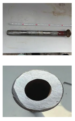
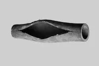
The overall macroscopic appearance of the failed serpentine tube, along with the morphology at the elbow, is shown in Figure 1.
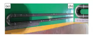
Figure 1. Macroscopic morphology of a serpentine bend
To determine the cause of the failure, specimens were collected from selected sections of the tube for analysis. A schematic diagram of the sampling locations is shown in Figure 2. Specimen 6″ was prepared for metallographic examination, while specimens 1–6 were used for hardness testing. A schematic diagram of the sampling locations is shown in Figure 2. Specimen 6″ was prepared for metallographic examination, specimens 1–6 were used for hardness testing, specimens 7 and 8″ were full-tube tensile specimens, specimen 9 was designated for chemical analysis, and specimen 10* was a bend test specimen.
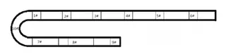
Figure 2. Schematic diagram showing the sampling locations of the serpentine tube
2. Physical and Chemical Testing and Macroscopic Analysis
2.1 Chemical Analysis
Specimen 9# was analyzed using a direct-reading spectrometer, and the results confirmed that its chemical composition met the requirements for 20G steel pipes as specified in GB/T 5310.
2.2 Mechanical Property Testing
The yield strength ratio is a critical parameter influencing the quality of steel pipes during forming and bending. Whole-pipe tensile tests were conducted on specimens 7 and 8*. The measured yield strength, tensile strength, and elongation at fracture all met the requirements for 20G steel pipe specified in GB/T 5310. In addition, the yield strength ratios were all above 0.6, indicating a good balance between yield strength and tensile strength, which minimizes the risk of failure caused by inadequate plastic deformation.
2.3 Macro and Micro Analysis
2.3.1 Macro Analysis
Based on specimen 10″ shown in Figure 2, two serpentine tube samples exhibiting pronounced wrinkles at the elbow were selected for analysis.
2.3.2 Micro Analysis
Metallographic examinations were conducted on specimens 1–6* and 2–6*. The microstructure consisted of ferrite and pearlite (F+P) with a uniform grain size of 8.5. The grains were uniformly distributed, and no decarburization was observed on the inner or outer walls. These results met the requirements for microstructure, grain size, and decarburization layer of 20G steel as specified in GB/T 5310-2008 and the procurement specification.
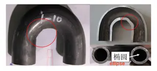
Figure 3. Wrinkles at the elbow bend point
Wrinkling at the elbow can disrupt fluid flow, destabilize hydrodynamics, and potentially lead to failure. Optimizing the bending process—such as using hot bending instead of cold bending—effectively reduces residual stress in the elbow. Additionally, reducing the clamping force on the bend-starting side prevents metal buildup, ensures proper material flow, and produces a smooth, wrinkle-free inner bend. Because small-diameter serpentine elbows undergo substantial deformation during bending, this area is a structural weak point during both manufacturing and operation. The outer bend experiences significant thinning due to tensile stress, and prolonged fluid erosion can further reduce the wall thickness. Ultimately, if the wall strength falls below the internal pressure, plastic deformation may occur, potentially causing elbow rupture.
3. Other Common Failure Types
Compared with the hydrodynamic instability caused by elbow wrinkling, severe thinning and cracking of the elbow are the primary causes of pipeline failure and rupture.
3.1 Elbow Thinning
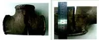
A typical specimen exhibiting elbow thinning was selected for analysis. The overall morphology of the failed component is shown in Figure 4(a). The center of the burst is located on the outer side of the elbow, approximately 28 mm from the crown, with a rupture length of 20 mm. The affected area is roughly 7 mm wide and shows characteristic swelling and tearing along the rolling direction. The crack morphology at the elbow is shown in Figure 4(b). A red oxide scale is present on the outer surface of one side of the elbow, while the inner wall of the crack, sectioned along the longitudinal axis, appears smooth and free of corrosion. At the outer bend, the wall thickness is reduced to approximately 2.4 mm due to tensile stress, whereas the inner bend has a thickness of about 4.3 mm as a result of metal accumulation under compressive stress. This indicates that the crack originated from the outer wall of the tube, where progressive thinning eventually reduced the wall strength below the internal pressure, resulting in failure. A hole approximately 7 mm in diameter formed, and due to the significant wall thinning at this location, the crack propagated outward from its center along the rolling direction.
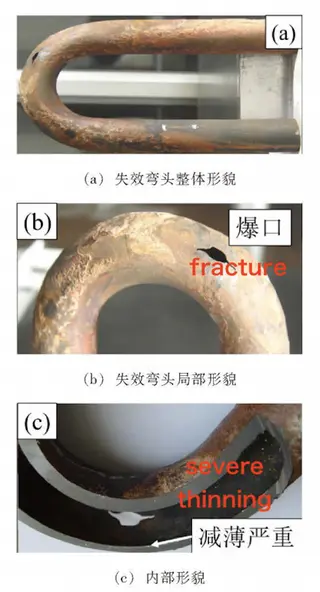
Figure 4: Leakage at the elbow of a failed sample tube
(a) Overall appearance of the failed elbow (b) Local features of the failed elbow (c) Internal features
Metallographic specimens were taken from both the straight section of the elbow and the fracture site. After coarse grinding, fine grinding, and polishing, the specimens were examined using an Axiovert 200 MAT microscope. Observations of non-metallic inclusions, grain size, and microstructure showed that inclusions of types A, B, C, D, and Ds were all below grade 1, the grain size was grade 8, and the microstructure consisted of ferrite and pearlite (Figures 5(a) and 5(b)). The distal straight-section specimen displayed an intact microstructure, fully meeting the requirements for 20G steel pipe as specified in GB/T 5310. However, at the rupture site, the grains were elongated along the rolling direction, clearly indicating tensile deformation of the microstructure caused by localized thinning, thickening, and severe deformation in the fracture zone.
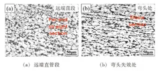
Figure 5: Microstructure
(a) Distal straight pipe section (b) Failed area of the elbow
3.2 Elbow Cracks
For steel pipes with relatively low yield strength, in addition to wrinkling caused by poor metal flow during serpentine bending and fluid leakage due to yield strength being lower than the internal pressure, excessive hardness and strength may also develop at the elbow. This usually occurs as a result of overly rapid cooling during heat treatment or pronounced work hardening during the bending process. As the outer bend of the elbow thins, the pronounced hard–brittle effect can cause cracks to initiate and propagate, either during bending or in service, ultimately resulting in crack-type failure. The macroscopic morphology of this type of failure is shown in Figure 6. Figure 6(a) illustrates a crack on the outer side of the elbow, while Figure 6(b) shows the crack on the inner wall of the elbow.
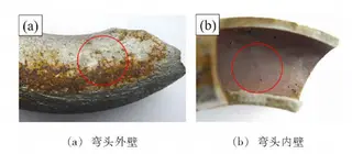
Figure 6. Macroscopic Morphology of Elbow Crack Failure
(a) Elbow outer wall (b) Elbow inner wall
4. Analysis and Discussion
Based on the three typical failure morphologies of serpentine heat exchanger tubes described above, the possible causes of elbow failure can be summarized as follows: First, excessive clamping force on the bend side during bending can result in poor metal flow and wrinkling, often caused by improper or unsuitable bending tooling. Second, an excessively high bending speed can prevent the metal from recovering adequately, leading to pronounced thinning on the outer bend. Alternatively, selecting an insufficient wall thickness can leave the thinned outer bend unable to withstand internal pressure, ultimately causing tube failure. Third, excessively high bending speeds can generate significant residual stresses, while low yield strength can lead to insufficient deformation resistance, both of which may ultimately cause cracks to develop in the elbow during bending.
5. Conclusions and Preventive Improvement Measures
- To reduce wrinkling at bend points, the clamping force on the bending side should be properly lowered to ensure uniform metal flow and prevent wrinkles caused by localized material accumulation.
- To address thinning on the outer bend of the elbow, the bending speed should be reduced to allow the metal adequate recovery time. Alternatively, thicker material can be specified during the design stage to minimize post-bending wall thinning.
- To prevent cracking from excessive bending speeds, the deformation rate should be reduced, allowing the material sufficient time for plastic recovery.
- To minimize work hardening and residual stress during bending, hot bending can be applied at the elbow, enhancing metal plasticity, relieving residual stress, and reducing the risk of cracking.
- During process execution, inspection and quality control should be reinforced to promptly detect and correct defects, ensuring the quality of elbow forming and long-term service reliability.
Send your message to this supplier
Related Articles from the Supplier


Related Articles from China Manufacturers

Analysis of Boiler Tube Failure Due to Burst
- Dec 26, 2024

Analysis and Solution of Valve Failure Mode
- Oct 31, 2022
Related Products Mentioned in the Article
Supplier Website
Source: https://www.landeepipefitting.com/failure-analysis-of-heat-exchanger-tube-elbows-in-thermal-power-plants.html