Failure Analysis of Carbon Steel Elbow in Power Station Main Steam Pipe
Abstract: To enhance boiler safety, this paper analyzes a failure incident in the main steam pipe elbow of a self-contained power station boiler at a chemical fiber plant, caused by the improper use of carbon steel, which resulted in fracture and leakage. Through macroscopic inspection, wall thickness measurement, spectral analysis, metallographic examination, strength verification, and surface non-destructive testing—combined with a comparison between the failed elbow, adjacent straight pipe sections, and correctly selected nearby materials—it was determined that prolonged over-temperature operation led to severe pearlite spheroidization and graphitization in the elbow material, accompanied by localized creep crack formation, ultimately resulting in failure. Material selection plays a vital role in ensuring safe and reliable main steam pipeline operation.
Introduction: The main steam pipeline of a power station boiler runs from the outlet of the final-stage superheater to the steam turbine and operates under high temperature and pressure for prolonged periods. Therefore, material selection must adhere to relevant standards, including the Regulations on Safety Technical Supervision of Steam Boilers and DL/T 715-2015 Guidelines for the Selection of Metallic Materials in Thermal Power Plants. For medium- and high-pressure boilers, the main steam pipeline is typically constructed from high-alloy steel that offers adequate high-temperature strength, structural stability, and oxidation resistance. Both material selection and installation must be overseen by authorized special equipment inspection agencies. Research indicates that the use of low-grade carbon steel during installation—effectively subjecting the pipeline to prolonged over-temperature conditions—significantly accelerates creep deformation, degrades mechanical properties, and increases the risk of rupture. In the event of leakage or rupture, the consequences can be severe. Although strict regulatory standards and robust quality assurance systems are in place for both manufacturers and installers, factors such as lengthy production and installation cycles (ranging from six months to as long as two to three years), inadequate on-site material management, and the common use of economical carbon steels like 20G in low-temperature sections can increase the risk of material mix-ups—particularly due to the similar appearance of different steel grades.
The inadvertent use of lower-grade materials in high-demand applications can lead to rapid failure or even pipeline rupture. This paper presents a case study of a main steam pipeline rupture incident at a chemical fiber plant. Through failure analysis of the leaking elbow and comparison with unaffected sections subjected to the same operating conditions, the investigation identifies material misapplication and prolonged over-temperature operation as the root causes. The study highlights the critical importance of proper material selection and standardized management in ensuring the safety and structural integrity of power station boilers.
1. Overview of the Accident
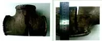
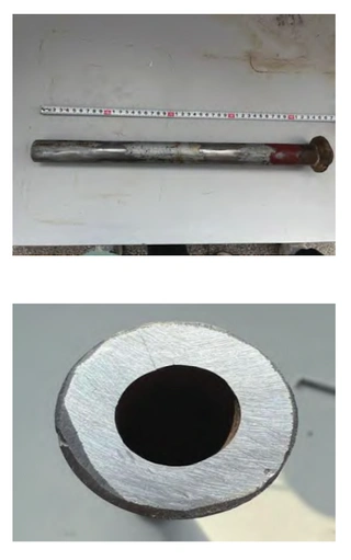
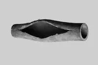
A 300 t/h self-contained power station boiler—a circulating fluidized bed, high-temperature, high-pressure unit with a main steam temperature of 540 °C and pressure of 9.8 MPa—at a chemical fiber plant experienced a failure only 10 months (approximately 7,200 hours) after commissioning. The main steam pipeline elbow of the thermal power unit ruptured, resulting in leakage. The failure site is shown in Figure 1, with photographs taken from two different angles. The leak occurred at the lower elbow of the vertical section of the main steam inlet branch pipe connected to the cylinder (ϕ245 mm × 20 mm, 12Cr1MoV), specifically at the elbow labeled “5” in Figure 2. The damaged elbow exhibited significant bulging and deformation.
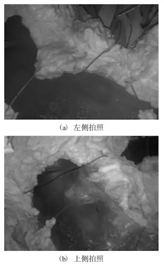
(a) Left-side view (b) Top view
Figure 1 Rupture and leakage of the main steam pipe elbow
2. Inspection and Testing
2.1 Macroscopic Inspection
Elbows 1 through 4 (see Figure 2), along with their adjoining straight pipe sections and butt welds, were thoroughly inspected. No noticeable bulging or cracking was observed. The oxide scale on the pipe surfaces was thin, rust-red in color, and easily peeled off. After removing the scale, the underlying metal surface appeared blue-black. Inspection of Elbow 5 revealed evident bulging and deformation along the inner curve. The measured diameter at the peak of the swelling was 275.5 mm, representing a 12.4% increase over the original 245 mm. A 12 mm-long rupture was found at the apex of the bulge.
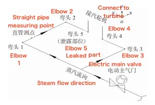
Figure 2 Main steam pipe main valve rear piping system
2.2 Wall Thickness Measurement
Wall thickness measurements were taken on the bulging section of Elbow 5, the outer curved surfaces of Elbows 1 to 4, and the adjoining straight pipe sections. Detailed results are presented in Table 1. The locations of Elbows 1 through 5 and their corresponding straight pipe sections are illustrated in Figure 2. As shown in Table 1, no significant wall thinning was observed in the straight pipe or in Elbows 1 through 4. However, a significant reduction in wall thickness was observed in the bulging area of Elbow 5, where the leakage occurred.
Table 1 Thickness of elbows and straight pipes
|
Test Location |
Thickness (mm) |
Test Location |
Thickness (mm) |
|
Elbow 1 |
20.1 |
Elbow 4 |
20.0 |
|
Elbow 2 |
20.4 |
Elbow 5 |
12.5 |
|
Elbow 3 |
21.0 |
Straight Pipe |
18.0 |
2.3 Strength Calculation
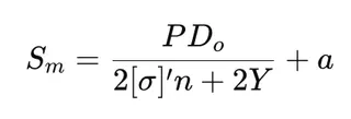
In accordance with DL/T 5054-2016 Technical Regulations for the Design of Steam and Water Pipelines in Thermal Power Plants, the minimum required wall thickness for the steam turbine inlet branch pipe—located near the leakage site—was calculated using the following formula:
Where:
Sm = Minimum required wall thickness of the straight pipe (mm)
P = Design pressure (MPa)
Do = Outside diameter of the pipe (mm)
[σ]′ = Allowable stress at the design temperature (MPa)
n = Stress correction factor
Y = Temperature correction factor
a = Additional thickness allowance for corrosion, erosion, etc. (mm)
The calculated minimum required wall thickness for the steam turbine’s main steam inlet branch pipe is 15.2 mm. The actual measured wall thicknesses of all elbows and straight pipe sections comply with the requirements of DL/T 5054-2016.
2.4 Spectral Analysis
The WK-4 spectrometer was used to perform semi-quantitative analysis on five elbows and straight pipes. The process adhered to the DL/T 991-2006 standard, Technical Guidelines for Metal Spectral Analysis of Power Equipment, and the quality standard applied was GB5310-2008, Seamless Steel Pipes for High-Pressure Boilers. The results showed that, except for Elbow 5, the materials of the other components generally matched the specified materials. Elbow 5 was found to contain seven elements: Cr, Mo, V, Ni, Ti, W, and Mn. The analysis concluded that Elbow 5 was made of carbon steel, which initially explained the cause of the rupture and leakage. According to DL/T 715-2015, Guidelines for the Selection of Metal Materials for Thermal Power Plants, carbon steel 20G is suitable for steam pipes and headers with wall thicknesses operating at temperatures up to 430°C. Similar provisions are outlined in TSGG0001-2012, Regulations on Boiler Safety Technical Supervision (Section IV). However, the design operating temperature of the main steam pipe is 540°C, which significantly exceeds the allowable temperature range for this material. As a result, the pipe’s metal structure underwent significant degradation. Prolonged over-temperature operation of the low-grade carbon steel elbow was identified as the primary cause of the accident.
2.5 Hardness Test
The hardness of the back arc surfaces and straight pipe sections of each elbow was tested separately. The specific test results are presented in Table 2.
Table 2 Hardness of Each Elbow and Straight Pipe
|
Test Locations |
Hardness (HB) |
Test Locations |
Hardness (HB) |
|
Elbow 1 |
160 |
Elbow 4 |
153 |
|
Elbow 2 |
158 |
Elbow 5 |
142 |
|
Elbow 3 |
170 |
Straight Pipe Section |
161 |
As shown in Table 2, after high-temperature operation, the hardness of Elbow 5 decreased significantly compared to its value before commissioning. Although the hardness of the other parts also declined to some extent, it remained within the normal range.
2.6 Metallographic Structure
Five locations—Elbows 1 through 4 and one straight pipe measurement point (see Figure 2)—were selected at and around the leakage site for on-site composite metallographic structure inspection. The inspection sites were mechanically polished and then etched with a nitric acid-alcohol solution. Metallographic structure images are shown in Figure 3.
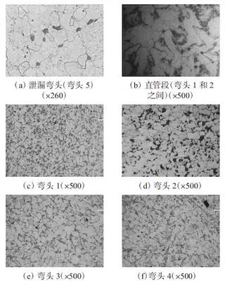
(a) Leaking elbow (elbow 5) (×260) (b) Straight pipe section (between elbows 1 and 2) (×500)
(c) Elbow 1 (×500) (d) Elbow 2 (×500) (e) Elbow 3 (×500) (f) Elbow 4 (×500)
Figure 3. Metallographic structure images of each test point
As shown in Figure 3(a), the metallographic structure of the leaking part exhibits severe deterioration. Its microstructure consists of ferrite, granular carbides, and graphite, with creep cracks appearing between the grains. It shows pearlite spheroidization at level 5 and graphitization at level 2. Figures 3(b) through 3(f) indicate that no intergranular creep cracks or severe creep damage were observed in the metallographic structures of the other inspected locations. The aggregated pearlite (or bainite) regions have begun to disperse but remain relatively compact, preserving their original regional morphology. According to DL/T 773-2016, Spheroidizing Rating Standard for 12Cr1MoV Steel for Thermal Power Plants, the metallographic structure’s spheroidization level is rated as Level 2, indicating slight spheroidization.
2.7 Surface Non-Destructive Testing
In accordance with NB/T 47013-2015, Non-Destructive Testing of Pressure Equipment, all back arc surfaces of the elbows were polished to reveal their metallic luster. Magnetic particle testing was performed on all back arc surfaces using a ZCM-DX1203A magnetic particle flaw detector. No detectable magnetic indications or defects were found on any of the elbows’ back arc surfaces.
3. Test Results, Corrective Measures, and Suggestions
3.1 Test Results and Corrective Measures
After appearance inspection, thickness testing and strength calculation, spectral analysis, metallographic structure examination, and surface non-destructive testing, no obvious abnormalities were found in Elbows 1 to 4 and the straight pipe section (see Figure 2). These pipes were used properly, showed no signs of excessive aging, and can continue in service. Replace the burst elbows with materials that meet the correct specifications, and re-test the materials prior to installation. Use qualified welding procedures to weld the two butt joints of the elbows. After welding, perform post-weld heat treatment in accordance with DL/T 819-2010, Technical Regulations for Welding Heat Treatment of Thermal Power Plants. Additionally, perform buried defect detection in accordance with NB/T 47013-2015, Non-Destructive Testing of Pressure Equipment.
3.2 Suggestions
During boiler operation, the operator should increase inspection frequency to prevent over-temperature and over-pressure conditions in the main steam pipeline. Take advantage of unit shutdowns to periodically conduct macro-level self-inspections of newly replaced main steam pipe elbows and welds. During routine boiler inspections, the inspection agency should prioritize the main steam pipe elbows in the steam engine room as key components, conducting macroscopic, microscopic, and non-destructive testing. If necessary—such as in cases of main steam pipe bulging deformation, weld cracks, or leakage—the design unit should be asked to recalculate the stresses on the main steam pipe system and review the pipe supports and hangers, making adjustments as needed to ensure that system stresses remain within allowable limits.
4. Failure Cause Analysis
The main steam pipeline of the self-contained power station boiler has been in operation under high-temperature, high-pressure conditions for an extended period. Over time, the metallographic structure of the pipeline material undergoes changes such as pearlite spheroidization, graphitization, and redistribution of alloying elements within the steel. Under normal boiler operating conditions, these metallographic transformations proceed very slowly. If the appropriate grade of heat-resistant steel is selected based on the main steam pipe’s operating parameters during design, fabrication, and installation, the pipe’s microstructure will remain essentially stable throughout its design life, and its mechanical properties will continue to meet long-term service requirements under the specified conditions. However, a low-grade carbon steel elbow was mistakenly installed on the main steam pipeline, subjecting it to operating conditions far beyond its design limits. The design operating temperature of the main steam pipe at the chemical fiber plant’s power station is 540°C. However, due to the improper use of carbon steel elbows, these elbows were exposed to overtemperature conditions for approximately 10 months (7,200 hours). Under these conditions, the pipe’s microstructure underwent severe degradation, making rupture and leakage inevitable. The graphitization process in carbon steel is influenced by several factors, including temperature, stress, welding, and chemical composition. However, temperature is the primary cause of this failure. According to DL/T 715-2015 Guidelines for the Selection of Metal Materials in Thermal Power Plants, carbon steel 20G offers adequate strength and oxidation resistance at temperatures below 450°C. However, prolonged exposure to temperatures between 470°C and 480°C can result in pearlite spheroidization and graphitization. Therefore, prolonged over-temperature operation was the primary cause of the failure. Under prolonged exposure to high-temperature stress, the lamellar cementite in the pearlite structure of 20G steel transforms into spheroidized cementite, which has lower free energy. As the main steam pipe continues to operate at elevated temperatures, the amount of carbide particles increases. In the early stages of creep damage, microstructural changes are characterized by the fine precipitation of carbides along grain boundaries or within ferrite grains. With an increase in carbide content, enlargement and progressive spheroidization of pearlite regions occur. At high temperatures, a characteristic metallographic phenomenon occurs in carbon steel: supersaturated carbon atoms migrate and aggregate to form free carbon atoms, which then convert into graphite. Graphitization typically results from the decomposition of pearlite (Fe + Fe₃C) into an equilibrium structure consisting of iron and graphite. Since graphite is very weak and forms as flaky structures within pearlite, the material’s strength decreases significantly while its brittleness increases. Once the misapplied carbon steel elbow undergoes significant graphitization, its strength can no longer withstand high pressure, ultimately leading to failure, fracture, and leakage.
5. Conclusion
Based on the inspection and analysis of the rupture and leakage site of the 300th main steam pipe elbow in the self-contained power station boiler at a chemical fiber plant—caused by the improper use of carbon steel—and the surrounding areas subjected to the same operating conditions, the following conclusions were drawn:
- The burst and leaking elbow was fabricated from carbon steel, representing a clear instance of improper material selection.
- The carbon steel elbow had been in service for only 10 months (7,200 hours) and was continuously exposed to an overtemperature of 110°C. Its metallographic structure underwent severe pearlite spheroidization, graphitization, and intergranular creep cracking, which were the primary causes of the failure.
- Under operating conditions of 540 °C and 9.8 MPa, the carbon steel elbow experienced severe metallurgical degradation—such as pearlite spheroidization, graphitization, and intergranular creep cracking—ultimately leading to rupture and leakage. In contrast, the metallurgical changes in the alloy steel 12Cr1MoV elbow remained within controllable and expected limits. This underscores the critical importance of proper material selection in ensuring the safe operation of boilers under high-temperature and high-pressure conditions.
Send your message to this supplier
Related Articles from the Supplier


Related Articles from China Manufacturers

Analysis of Boiler Tube Failure Due to Burst
- Dec 26, 2024

Analysis and Solution of Valve Failure Mode
- Oct 31, 2022

Related Products Mentioned in the Article
Supplier Website
Source: https://www.landeepipefitting.com/failure-analysis-of-carbon-steel-elbow-in-power-station-main-steam-pipe.html