Innovations in Pipe Welding Technology, Equipment, and Quality Inspection
1.1 Advanced Welding Technology
The development of automatic welding technology of pipes began in 1958, when Price Company in the United States developed the first set of automated welding equipment. In 1969, Kraus Company introduced the CRC welding machine. In 1972, the former Soviet Union developed flash welding technology, which significantly advanced submarine pipeline welding. In the same year, Japan introduced a computer-controlled automatic welding system. In 1978, France jointly developed the Shixing automatic welding machine, which was applied in submarine pipeline welding tests. These pioneering technologies laid a solid foundation for the global advancement of automated welding. By the 21st century, pipeline automatic welding technologies abroad had become highly advanced—particularly in North America, where over 85% of pipeline construction employed automatic welding. Among the notable developments, the CRC company in the United States developed a multi-torch automatic welding system that includes a groove beveling machine, an internal welding machine, and a dual-torch external welding machine. This system has been used to weld over 34,000 kilometers of pipelines worldwide, demonstrating excellent adaptability to a wide range of construction environments. In addition, companies such as Fronius (Austria), Serimax (France), and PWT (Italy) have developed their own advanced automatic welding systems. International investment in pipeline welding research continues to grow, with a particular focus on optimizing the deposition rate, welding speed, and environmental impact of submerged arc welding (SAW). As high-strength steel becomes more widely used, traditional processes such as shielded metal arc welding (SMAW) and gas metal arc welding (GMAW) are increasingly being supplemented by advanced methods like electron beam welding (EBW) and laser welding. EBW offers low heat input and high efficiency, but its use is limited by the requirement for high-vacuum environments. Meanwhile, China’s welding technology is evolving rapidly. In high-strength steel pipeline applications, hybrid laser-arc welding (HLAW) has demonstrated great potential. By combining the deep penetration of laser welding with the stability of arc welding, HLAW enables faster welding speeds, greater penetration depth, lower heat input, and improved weld microstructure and toughness. Extensive experiments conducted in China have confirmed the suitability of HLAW for automated pipeline welding in complex site conditions. Although HLAW equipment is relatively expensive, its long-term benefits—such as reduced repair rates and increased productivity—make it a compelling option with broad future prospects. Another emerging technology is annular friction welding (FRIEX), which has attracted attention in mountainous pipeline construction projects. This technique uses the rotational friction of a specially designed welding ring to generate heat and join pipes without melting the material. As a result, it minimizes deformation and eliminates solidification defects. FRIEX does not require filler materials or shielding gases, making it especially well-suited for high-altitude and rugged terrain applications where safety and efficiency are critical. While further research is needed to fully understand the microstructural mechanisms of FRIEX, it has already demonstrated significant potential for wider application in challenging environments. In general, foreign pipeline welding technologies are becoming increasingly industrialized and tailored to specific applications. For instance, fully automatic submerged arc welding offers high deposition rates, fast welding speeds, and minimal emissions; electric ring welding is designed specifically for vertical configurations; and high-speed friction welding presents a novel approach to plate joining by using plastic bonding generated from frictional heat.
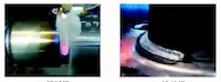
Figure 1 presents a range of advanced welding technologies developed in recent years. These technologies are primarily designed to optimize welding processes under specific or challenging conditions and show strong potential for future development. In addition, several specialized welding techniques—such as underwater welding, Cold Metal Transfer (CMT), and laser welding—are currently in the research and development phase and are expected to play a more significant role in future applications. Overall, both domestic and international research efforts show that various innovative welding methods have made substantial progress in both scientific research and practical application. These advancements provide a wide array of technical options and strong support for future welding projects.
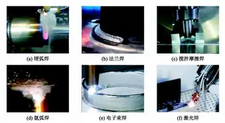
(a) Submerged Arc Welding (b) Flange Welding (c) Friction Stir Welding
(d) Argon Arc Welding (e) Electron Beam Welding (f) Laser Welding
Figure 1 Various Advanced Welding Technologies
1.2 Pipeline Welding Equipment
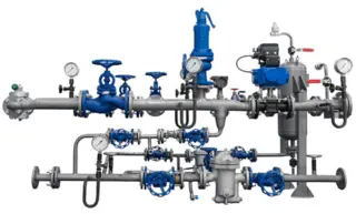
Different welding methods require corresponding types of equipment. Among these, automatic welding systems are the most complex, comprising numerous components and intricate mechanical devices. Automatic welding equipment generally includes internal welding machines, external welding machines, and various auxiliary devices such as beveling machines, heating systems, and guide rails. As automatic welding technology advances, the technical specifications and performance of welding equipment have also improved. Leading external welding machines include the P260, M300, and P600 series developed by CRC in the United States (see Figure 2), as well as systems from NOREAST (UK), RMS (Canada), and PWT (Italy). In China, the PAW2000 and PAW3000 series, developed by the PetroChina Pipeline Bureau, are the primary domestically manufactured models.
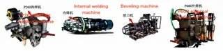
Figure 2 CRC P600 Fully Automatic Pipeline Welding Equipment
For internal welding, widely used machines include the CRC-IWM from CRC (USA), NOREAST-IWM (UK), and domestically produced models such as the CPP-IWM, IW48, and Sichuan Xionggu A-810, all developed by the PetroChina Pipeline Bureau. The beveling machine is also a critical component of automatic welding systems, designed to prepare pipe ends with precise weld bevels to ensure optimal joint quality. Well-known models include the CPP900-FM from the PetroChina Pipeline Bureau, the CRC PFM (USA), and the Grei beveling machine (Italy). In addition, a wide range of pipe alignment and fit-up tools are used to ensure precise positioning of pipes prior to welding. Table 1 presents a selection of commonly used advanced pipe alignment systems from both domestic and international manufacturers. Within automatic welding technology, a more advanced category of equipment is the welding robot. These robots, adapted from industrial robotic systems, are designed to perform specialized welding tasks (see Figure 3). Currently, the most advanced welding robots are primarily used for circumferential (circular) welding. Leading manufacturers in this field include CRC and MAGNATECH from the United States, as well as VIETZ from Germany.
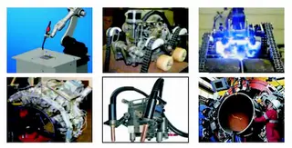
Table 1 Common Welding Adapter Models
|
Model |
Type |
|
CC400-S PLUS by Lincoln Electric (USA) |
Manual |
|
ZX7-400ST by Jinan Aotai Group |
Manual |
|
XMT-304 by Miller Electric (USA) |
Manual |
|
ZX7-400B (PE21-400) by Beijing Time Group |
Manual |
|
DC400 Power Source with LN-23P Feeder by Lincoln Electric (USA) |
Semi-automatic |
|
D7-500 Power Source with XG-90 Series Feeder by Sichuan Xionggu |
Semi-automatic |
|
XMT-304 Power Source with S-32P Feeder by Miller Electric (USA) |
Semi-automatic |
In addition, Brazilian researchers have developed a chain-driven pipeline welding robot. The P625 pipeline welding robot, developed by CRC-EVANS in the United States, offers more accurate path tracking. RTD in the Netherlands has invented the Rotoscan automatic ultrasonic inspection system, which can accurately detect weld positions. SERIMAX in France has developed a four-head, dual-torch welding robot that significantly improves welding efficiency. J. Ray McDermott, also from the United States, invented the JAWS welding system, which enables coordinated operation of multiple devices. Some common foreign manual and semi-automatic welding equipment, along with their corresponding models, are listed in Table 2. At present, with advancements in inverter power supply technology and the application of collaborative control systems, double-wire, double-arc molten pool gas-shielded welding has emerged as a research hotspot due to its exceptionally high welding efficiency. This has led to the development of two primary double-wire welding technologies: Twinarc and Tandem. In the field of pipeline welding, Miller (USA) and Cloos (Germany) have each developed their own double-wire welding systems. Figure 4(a) shows the Twinarc double-wire welding system developed by Miller, which uses two identical welding power supplies and two wire feeding mechanisms that feed wires into the same contact tip, creating a eutectic pool in the arc. However, this system has structural drawbacks, including poor arc stability, significant arc interference, and difficulty precisely controlling both arcs and droplet transfer. Figure 4(b) illustrates the Tandem high-speed double-wire pulsed welding technology developed by Cloos. Its design features two wire feeding systems that deliver wires into a dual-nozzle torch, each powered by an independent welding power source. This setup allows for separate adjustment of parameters for each wire during welding. According to available reports, CRC in the United States has successfully collaborated with Fronius to develop a double-wire Tandem seam welding device, as shown in Figure 4(c).
|
Model |
Type |
|
Manual Lever-Type External Line-Up Clamp by H&M (USA) |
Manual |
|
Hydraulic External Line-Up Clamp by Mathey |
Hydraulic |
|
Chain-Type External Line-Up Clamp with Bent Plate by H&M (USA) |
Chain-Type |
|
Lightweight Chain-Type External Line-Up Clamp by Mathey |
Chain-Type |
|
Line-Up Clamp by WELD-TECH (Denmark) |
Hydraulic and Manual |
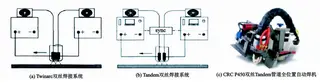
(a)Twinare double wire welding system (b) Tandem double wire welding system (c) CRC P45
Figure 4 Double wire double arc eutectic pool gas shielded welding technology
1.3 Pipeline Welding Defect Detection and Evaluation
Welding defects are inevitable during pipeline construction. Common defects in girth welds of long-distance pipelines include incomplete penetration, lack of fusion, slag inclusions, and porosity. Weld undercutting and sinking pose serious risks to the safe and reliable operation of pipelines, making defect detection and control especially critical. These issues often result from substandard welding materials, improper procedures, or inadequate techniques. Addressing different types of welding defects requires targeted preventive measures, thorough cause analysis, and carefully designed repair plans. Traditional pipeline welding inspection methods often involve cutting or damaging the pipeline. While these methods may meet inspection standards, they compromise the structural integrity of the pipeline. Non-destructive testing (NDT), which evaluates welds without causing damage, has become the most widely adopted technique for pipeline welding inspection. Among NDT methods, X-ray inspection is one of the most effective, as it uses X-rays to penetrate materials and reveal internal flaws. While radiographic testing can detect a wide range of welding defects, its effectiveness decreases in thick-walled pipelines. Radiographic methods include traditional RT, computed radiography (CR), and digital radiography (DR). The primary differences lie in their imaging technologies and detection clarity. The appropriate method should be selected based on the specific requirements of each construction project. Ultrasonic testing (UT) is another key NDT technique that detects internal defects by analyzing the reflection of ultrasonic waves at material interfaces. It is particularly effective at detecting flaws within base materials and weld zones, although its performance diminishes when inspecting crystalline materials. Current ultrasonic testing methods include AUT (Automated Ultrasonic Testing), PAUT (Phased Array Ultrasonic Testing), and TOFD (Time-of-Flight Diffraction). Each method operates on different principles and serves distinct applications, so the appropriate method should be selected accordingly. Other non-destructive testing techniques also provide valuable capabilities in pipeline welding inspection. Magnetic particle testing (MT) is effective for detecting surface defects, while penetrant testing (PT) is suitable for identifying porosity, inclusions, and surface cracks.
According to failure statistics in pipeline construction, girth-welded sections experience greater stress and strain, making the evaluation of welding defect failures critically important. Numerous researchers have proposed various defect assessment methods. For example, Hui Yang et al. used finite element modeling to analyze the ultimate bearing capacity of cracked pipelines and evaluated defects according to the strain limit formula specified in the CSA Z662-2011 standard. Kejiang Han et al. examined large-scale yielding fractures in pipelines and proposed a strain-based evaluation method derived from the driving force equation and crack tip opening displacement. Bin Chen et al. conducted a comparative analysis of extensive girth weld data and performed quality assessments based on serviceability criteria. Traditional pipeline failure evaluation methods are largely based on the Failure Assessment Diagram (FAD) initially developed by the British Central Electricity Generating Board. Today, evaluation techniques based on this model are relatively mature; however, most do not account for variations in pipeline material properties. Based on studies of X65 steel, Lee analyzed the discrepancies between conventional assessment curves and those adjusted for specific material properties, highlighting the key differences influenced by material behavior. Similarly, Cravero et al. conducted burst pressure tests using the FAD method and developed a more accurate evaluation curve tailored to specific material properties.
Many Chinese researchers have also investigated pipeline failure assessment, primarily using traditional FAD curves. For example, Yongbo Shao et al. studied defects in T-joint pipelines and compared conventional and defect-specific assessment curves, finding that defect size is inversely proportional to the safety margin indicated by traditional curves. Zhenyong Zhang et al. focused on the toughness evaluation of girth welds, developing a methodology that provided technical support for large-scale projects such as the West-East Gas Pipeline (Phase III) and the China–Russia East-Route Pipeline. At present, evaluation methods for certain pipeline defects—such as those encountered in the Huanghe project—are still under investigation. Due to the complexity of pipeline welding projects and the influence of multiple interacting factors, evaluation methods must be tailored to specific project conditions to ensure accurate and reliable assessments.
Send your message to this supplier
Related Articles from the Supplier
Related Articles from China Manufacturers


Related Products Mentioned in the Article
Supplier Website
Source: https://www.landeepipe.com/innovations-in-pipe-welding-technology-equipment-and-quality-inspection.html