Structural Performance Analysis of Zirconium Pressure Vessel Lap Joint Flanges
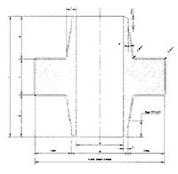
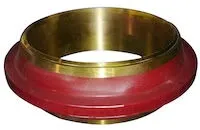
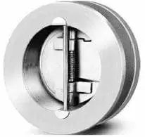
Abstract: This study investigates the stress distribution in lap joint flanges of zirconium pressure vessels with different liner ring structures using ANSYS 11.0 software. The analysis identifies the areas of maximum stress and evaluates the performance of various liner ring configurations. Drawing on the stress analysis, this study discusses the strengths and weaknesses of each structural configuration and offers recommendations for selecting appropriate liner ring designs based on specific operating conditions. The results provide a valuable reference for engineering applications. The use of zirconium equipment in industrial applications has grown significantly, primarily due to its superior resistance to corrosion in highly corrosive media. Its primary applications are found in nuclear reactors and chemical processing systems, where it is used in components such as pressure vessels, heat exchangers, towers, and agitators. Pure zirconium (Zr) exhibits a melting point of approximately 1845 °C, a boiling point of around 3577 °C, and a phase transition temperature of 862 °C. Above this temperature, zirconium adopts a body-centered cubic (β-phase) crystal structure, while below it, it transitions to a hexagonal close-packed (α-phase) structure. Among zirconium alloys, Zr-3 is the most widely used in industrial applications. Due to the high cost of zirconium, Lap joint flanges are commonly used in zirconium pressure vessels, enabling the flange body to be fabricated from carbon steel or stainless steel to reduce material expenses. A schematic of the Lap joint flange structure is presented in Figure 1.
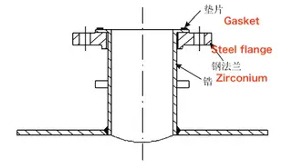
Figure 1. Structure of the Lap joint flange for Zirconium Pressure Vessel
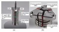
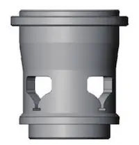
Depending on specific design requirements and manufacturing processes, the pipe and bushing structures in zirconium pressure vessels typically fall into several categories: integral flange bushings, single-sided welded flange bushings, double-sided welded flange bushings, butt-welded bushings, and inserted welded bushings, as illustrated in Figure 2.
This paper focuses on the various bushing configurations used in Lap joint flanges for zirconium pressure vessels. Through stress analysis, the regions of maximum stress are identified, and the advantages and disadvantages of each structural type are evaluated. The results aim to provide practical guidance for the engineering design of zirconium pressure vessels.
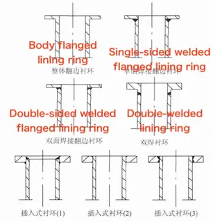
Figure 2. Bushing Structures
1. Stress Analysis
The upper section of the nozzle and the bushing, as shown in Figure 1, is selected as the object of study. The influence of the connection between the lower nozzle and the vessel cylinder is neglected. The stress distribution of the upper nozzle and bushing under operating conditions is illustrated in Figure 3. The axial force acting on the nozzle is calculated using the following equation:
![]()
Where:
Fa is the axial force on the nozzle (N),
R is the inner radius of the nozzle (mm),
and P is the internal pressure acting on the nozzle (MPa).
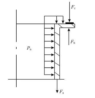
Figure 3. Stress schematic of the nozzle and bushing ring
The gasket is subjected to compressive force. To ensure effective sealing, the minimum compressive force required during operation is calculated as follows:

Where:
F is the minimum compressive force on the gasket (N),
Do is the diameter of the gasket’s load-bearing centerline (mm),
b is the effective sealing width of the gasket (mm),
m is the gasket factor,
P is the internal pressure (MPa).
In the pre-tightened state, with no internal pressure present in the pipe, the minimum compressive force on the gasket is expressed as follows:

Where:
y is the specific gasket seating stress (MPa).
Generally, the minimum clamping force on the gasket is determined by the pre-tightening condition, as this represents the maximum force the gasket experiences. Although the internal pressure during operation reduces the clamping force, it remains above the minimum required for sealing. Therefore, the stress condition is conservatively evaluated based on the minimum clamping force during pre-tightening.
As shown in Figure 3, the primary stresses in the pipe are axial and circumferential stresses resulting from internal pressure. The junction between the liner ring and the pipe is subjected to both gasket pressure and internal pressure, creating a stress concentration zone due to edge effects and bending moments. To assess stress distribution, a comparative analysis of various liner ring structures was conducted. The pipe considered has a nominal diameter of DN100, a design pressure of 1.6 MPa, and a design temperature of 150 °C. The material used is zirconium alloy (Zr-3), and the gasket is a non-metallic soft type. The analysis is performed using ANSYS 11.0, where an axisymmetric model is constructed to simulate loading conditions and evaluate the stress distribution. Figure 4 shows the stress nephogram (contour plot) of the integral flange bushing ring, while Figure 5 presents the corresponding stress nephogram for the single-sided welded flange bushing ring. For these two configurations, the bushing ring thickness matches that of the vessel wall. In butt-welded and inserted bushing designs, the ring thickness is 1.5 times that of the cylinder wall. The resulting stress distributions are shown in Figure 6.
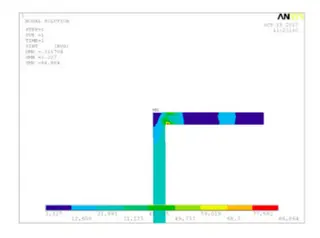
Figure 4. Stress nephogram (contour plot) of the integral flange bushing ring
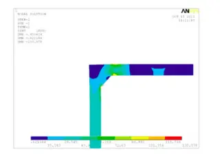
Figure 5. Stress nephogram (contour plot) of the single-sided welded flange bushing ring
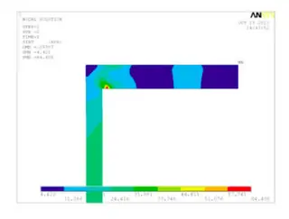
Figure 6. Stress nephogram (contour plot) of the butt-welded and plug-type bushing rings
2. Analysis of Calculation Results
Based on the stress distributions shown in Figures 4 to 6 and the comparative analysis of different liner ring structures illustrated in Figure 2, the following conclusions can be drawn:
- Due to the increased thickness of the liner ring in the butt-welded and inserted bushing structures, the maximum stress in these designs is relatively lower. Among these, the butt-welded liner ring structure is particularly favorable because its weld seam is located outside the high-stress region, making it a more optimal and reasonable design.
- Among the three inserted liner ring configurations, Inserted Liner Ring 3 (shown in Figure 2) is fully welded, providing better structural continuity than the other two non-integral designs. However, all its weld seams are located in high-stress areas, making any welding defects potentially detrimental to the service life of the liner ring structure.
- Compared to the single-sided welded flange liner ring, the integral flanged liner ring exhibits a lower overall stress level and contains no weld seams, thereby reducing the risk of stress concentration and fatigue failure. This makes the integral structure more reliable for long-term service.
3. Conclusion
- When manufacturing cost is not a constraint and operating pressure, gasket factor, and specific gasket seating stress are high, the butt-welded liner ring is the preferred choice. This structure allows for appropriate selection of cylinder and liner ring wall thicknesses based on stress analysis, ensuring the overall structure maintains a reasonable stress state.
- The integral flanged liner ring provides superior stress performance and is recommended when high reliability is essential. Under relatively mild operating conditions, a welded flanged liner ring or an inserted welded liner ring may be selected based on cost considerations.
Send your message to this supplier
Related Articles from the Supplier

Related Articles from China Manufacturers


Related Products Mentioned in the Article
Supplier Website
Source: https://www.landeeflange.com/structural-performance-analysis-of-zirconium-pressure-vessel-lap-joint-flanges.html