Multi-Directional Die Forging Process for Horizontal Valve Bodies with Dual Flanges
Abstract: In the multi-directional die forging of horizontal valve body forgings with flanges on both sides, achieving complete flange filling is often challenging, leading to a low yield of qualified parts. Simulation analysis of the forging process reveals that when the flanges are formed by horizontal punch extrusion, the metal initially flows toward the center of the die cavity. As resistance to flow at the center increases, the metal then begins to move into the flange cavities. However, the metal reaching the flange areas remains in contact with the die for an extended period, causing its temperature to drop and flow resistance to increase, which hinders complete filling of the flanges. To address this issue, a new process is proposed: forming both flanges using horizontal punch upsetting. This method reduces metal flow resistance, improves metal fluidity, and enhances the filling of the flanges on both sides of the valve body forging. Batch production results confirm the feasibility of this approach, demonstrating stable and reliable forging performance with a high qualification rate. Multi-directional die forging technology was first introduced by the American Cameron Company in the 1950s. It is a comprehensive process that combines extrusion with die forging. This technique enables the formation of complex-shaped forgings without flash, including those with multiple branches or internal cavities. Compared to conventional die forging, the multi-directional die forging process offers several key advantages:
(1) Material Savings
The multi-directional die forging process produces forgings without flash and with internal cavities, whereas conventional die forging typically yields solid structures with flash that must be removed through trimming. Consequently, material consumption in multi-directional die forging is significantly lower than in conventional forging.
(2) Reduced Machining Time
Conventional die forgings are solid and often require extensive machining to achieve the final product shape. In contrast, multi-directional die forgings closely approximate the final contour and often include internal cavities, significantly reducing the required machining time.
(3) Continuous Streamline of the Outer Contour
In conventional forging, flash formation interrupts the natural metal flow (streamline) and must be removed during trimming, which can compromise the integrity of the forging’s outer contour. In contrast, multi-directional die forging produces no flash, preserving a continuous and intact metal flow along the outer contour.
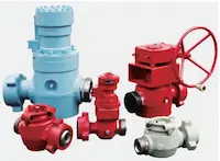
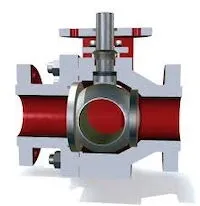
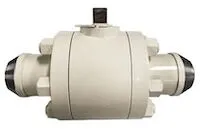
Valve body forgings with flanges on both sides are critical components of emergency shut-off valves. These parts are widely used across industries such as petroleum, natural gas, chemical processing, metallurgy, and electric power, playing a vital role in ensuring the safe operation of fluid pipeline systems. The working pressure range for these valve body forgings typically spans 25 to 42 MPa, with an emergency shut-off response time requirement of less than 2 seconds under both overpressure and underpressure conditions. During emergency shutdowns, the valve body undergoes significant vibrations, resulting in highly demanding operating conditions. Consequently, these forgings must meet strict requirements for mechanical properties and metallographic structure. When valve body forgings are produced using the multi-directional die forging process, their mechanical properties and metallographic structures generally exceed the required standards—especially elongation, which significantly surpasses specification limits. However, during production, fully filling the flanges on both sides of the valve body is often challenging, resulting in a low yield of qualified products. With an annual demand approaching 10,000 units, insufficient flange filling not only raises production costs but also impacts supply reliability. Therefore, it is essential to analyze the root causes of inadequate flange filling and develop effective solutions to improve product quality and reduce manufacturing expenses.
1. Introduction to Defects in Horizontal Valve Body Forgings with Flanges on Both Sides
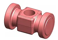
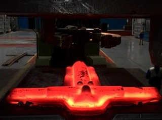
The material for the horizontal valve body forgings with flanges on both sides is 16Mn steel, with a weight of 76 kg per piece. The product’s shape is shown in Figure 1. These forgings are produced using a multi-directional die forging process, which simultaneously forms both horizontal flanges on either side as well as the vertical cavity in a single operation. During production, it has been observed that the flanges on both sides frequently remain incompletely filled, as shown in Figure 2. This incomplete filling results in a low acceptance rate for the valve body forgings, consequently increasing overall production costs.
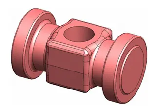
Figure 1. Shape of the valve body forging with flanges on both sides
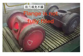
Figure 2. Incomplete flange filling on both sides of the valve body forging
(a) True strain (b) True strain (c) True strain (d) True strain (e) True strain (f) True strain
2. Analysis of the Causes and Solutions for Incomplete Flange Filling in Valve Body Forgings
To investigate the root causes of insufficient flange filling on both sides of the valve body forging, the forming process was simulated and analyzed using finite element analysis (FEA) software. The forging material is 16Mn steel. Prior to the simulation, a material model for 16Mn steel was established.
2.1 Material Model of the Forging Material
The material model for 16Mn steel was established based on compression tests conducted using a Gleeble thermal simulation testing machine. The applicable forging temperature range for 16Mn steel spans from 900 °C to 1200 °C. Accordingly, compression tests were carried out at temperatures of 900, 950, 1000, 1050, 1100, 1150, and 1200 °C. The corresponding strain rates applied during the tests were 0.05, 0.1, 0.5, 1, 4, and 6 s⁻¹. The resulting true stress–true strain curves for various temperatures and strain rates are presented in Figure 3.
2.2 Analysis of the Causes of Incomplete Flange Filling on Both Sides of the Valve Body Forging
The forming process of the valve body forging was simulated and analyzed using finite element analysis (FEA) software. Since the forging has a symmetrical shape along its longitudinal axis, a half-model (1/2 model) was used in the simulation to improve computational efficiency. The die material was defined as H13 steel, and the material model for the forging was derived from the true stress–true strain curves of 16Mn steel obtained at various strain rates and temperatures. The initial billet temperature was set to 1200 °C, and the die temperature was maintained at 200 °C. The die's idle speed was 40 mm/s, while the pressing speed was 25 mm/s. During the forging process, a non-graphite hot forging lubricant was applied. The friction coefficient between the billet and the die was 0.15, and the heat transfer coefficient between them was 8 N/(s·mm·°C). The forming process of the horizontal valve body forging with flanges is illustrated in Figure 4. During the horizontal punch extrusion process, the metal flow direction is illustrated in Figure 5. As the horizontal punch begins extruding the billet, most of the metal flows in the direction of the punch movement, advancing toward the center of the die cavity. Once the punch reaches a certain depth, resistance to further flow toward the center increases, causing the metal to redirect into the flange cavities on both sides and initiate flange formation. In the later stages of horizontal punch extrusion, the metal primarily fills the flange cavities on both sides of the forging. The temperature distribution at this stage is shown in Figure 6. At this stage, the metal in contact with the punch and the inner end face of the flange has cooled to below 800 °C, while the temperature on the outer end face and the curved surface of the flange has dropped to approximately 900 °C. Due to prolonged contact with the die, the metal in these areas loses significant heat, resulting in reduced fluidity and, consequently, insufficient filling of the outer edges of the flanges. This discrepancy explains why simulations indicate complete flange filling, while actual production experiences insufficient filling. The analysis shows that during horizontal punch extrusion, the metal initially flows toward the center of the die cavity. Once the flow resistance increases, the metal redirects into the flange cavities. However, the prolonged contact with the die causes the metal temperature in the flange areas to drop significantly, reducing fluidity and making it difficult to fully fill the outer edges of the flanges during the final forming stage.
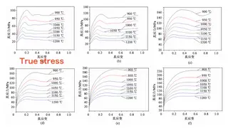
Figure 3. True stress–true strain curves at various strain rates and temperatures
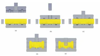
Figure 4. Simulation of the forging process
(a) Initial state (b) End of downward movement of the upper die (c) End of upper punch pre-positioning
(d) End of horizontal punch extrusion (e) End of upper punch penetration
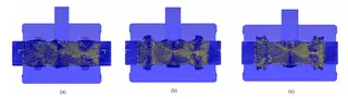
Figure 5. Changes in metal flow direction during horizontal punch extrusion
(a) Start of extrusion (b) Midway through extrusion (c) End of extrusion
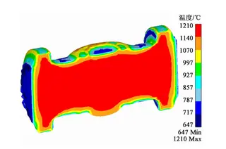
Figure 6 Temperature distribution of forgings after extrusion of flanges by horizontal punch
2.3 Solutions to the Incomplete Filling of Horizontal Flanges on Both Sides of the Valve Body Forging
As analyzed above, during the later stages of horizontal punch extrusion, the metal temperature drops and its fluidity decreases, resulting in insufficient filling at the outer edges of the flanges on both sides of the forging. To address this issue, the forming method for the horizontal flanges can be optimized by replacing horizontal punch extrusion with horizontal punch upsetting. With this adjustment, the die movement sequence during the forging process remains unchanged. Finite element simulation software was employed to simulate the upsetting process used to form the flanges on both sides of the valve body forging. The simulation preprocessing parameters are consistent with those described in Section 2.2 and will not be repeated here. The simulation results of the flange upsetting process using a horizontal punch are presented in Figure 7.
During the early stage of upsetting the flanges on both sides of the valve body forging with a horizontal punch, the metal does not contact the die and loses heat only through radiation to the air. As a result, the billet experiences minimal temperature drop. Additionally, when the flanges are formed by horizontal punch upsetting, the metal demonstrates significantly better fluidity compared to the punch extrusion forming process. The improved fluidity facilitates easier formation of the horizontal flanges on both sides of the valve body forging. By the end of the flange forming stage, the metal completely fills the flange cavities on both sides of the die. The upper punch then descends to create the vertical cavity of the valve body forging. As shown in Figure 7, during the initial stage of horizontal punch upsetting, the billet has minimal contact with the die cavity, which slows down the metal’s temperature loss. The metal fully fills the flange cavities, successfully forming the flanges on both sides of the valve body forging. The above simulation clearly shows that changing the flange forming method from horizontal extrusion to horizontal punch upsetting significantly reduces metal flow resistance, leading to improved flange formation on both sides of the forging.
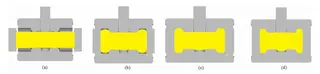
Figure 7. Process of horizontal punch upsetting of flanges on both sides of the forging
(a) Initial state (b) During billet upsetting (c) Flange upsetting (d) Center of upsetting die cavity
3. Batch Production Verification of Horizontal Valve Body Forgings with Flanges on Both Sides
During the mass production of horizontal valve body forgings with flanges on both sides, the billets are heated using a medium-frequency induction furnace. The billet heating temperature is set to 1200 °C, and the die is preheated to 200 °C. The press operation sequence during forging is as follows:
The upper die moves downward to close the die.
The upper punch descends to the top surface of the die cavity for pre-positioning.
The horizontal punch upsets the billet.
The upper punch performs piercing.
The upper punch retracts.
The upper die retracts.
The horizontal punch retracts.
The ejector pushes out the forging for demolding.
A robotic arm retrieves the forging, after which the ejector returns to its original position.
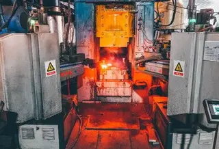
The production process is illustrated in Figure 8.
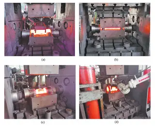
Figure 8. Batch production process of valve body forgings
(a) The billet is placed horizontally in the die cavity (b) The upper die is closed
(c) Forming is completed, and the forging remains in the lower die
(d) The robot retrieves the finished forging
During batch production, the filling quality of the horizontal flanges on both sides is shown in Figure 9. As illustrated, the flanges on both sides of each valve body forging are fully filled, meeting all technical specifications and quality requirements.
4. Conclusions
- When the flanges on both sides of the valve body forging are formed by horizontal punch extrusion, the metal initially flows toward the center of the die cavity. As resistance to flow increases in the central region, the metal begins to move toward the flange cavities on both sides. However, due to prolonged contact with the die, the metal at both ends of the billet experiences a significant temperature drop, which hinders metal flow during the later stages of extrusion. This results in incomplete filling of the outer portions of the flanges.
- Changing the forming method from horizontal punch extrusion to horizontal punch upsetting significantly improves the formation of the flanges. In the early stage of upsetting, the metal does not contact the die and loses heat only through radiation, resulting in a minimal temperature drop. This process reduces metal flow resistance, improves metal fluidity, and facilitates complete forming of the horizontal flanges on both sides of the valve body forging.
- Batch production results for valve body forgings confirmed the feasibility of the horizontal punch upsetting process used to form flanges on both sides. The process demonstrated stability and reliability, achieving a high rate of qualified forgings.
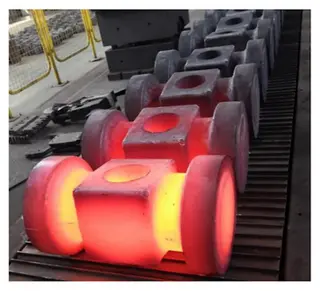
Figure 9. Formation of flanges on both sides of the valve body forging during batch production
Send your message to this supplier
Related Articles from the Supplier
Related Articles from China Manufacturers
What is Multi-Directional Die Forging?
- Feb 11, 2025
Guide to Multi-Directional Die Forging Technology
- Feb 04, 2026

Related Products Mentioned in the Article
Supplier Website
Source: https://www.landeeflange.com/multi-directional-die-forging-process-for-horizontal-valve-bodies-with-dual-flanges.html