Multi-Turn Valve Electric Actuator Operating Instruction
Please read this manual carefully prior using our product.
Please use our product correctly to avoid unnecessary damage and accidents! At the same time, the instructions specified in this manual must be strictly followed, as this machinery operates under industrial-level conditions with high current. While in use, if any exposed parts of the equipment are charged and can move or rotate simultaneously, it will be extremely dangerous. Unauthorized removal of the cap, improper use, incorrect operation, or maintenance may result in serious physical injury or damage to both personnel and the equipment.
Safety of the Equipment
The Following Rules Should Be Followed:
Only qualified personnel are authorized to operate this equipment.
While using the equipment, the relevant instruction manual and/or other product documentation must be readily available to ensure the requirements of this manual are followed.
Before powering on the equipment, please double-check that the input voltage, frequency, and connections are correct. The manufacturer will not be responsible for any motor damage caused by incorrect wiring or incorrect voltage.
The connection bolts for connecting valves should be at least Class 8.8.
The electric cabinet cap and motor seals should not be opened during cloudy or rainy days.
A special motor is used for the electric actuator, and its service life is limited. The continuous operation time should not exceed the duration specified on the nameplate.
When the equipment is not in regular use, it should be inspected, maintained, and activated on a regular basis. The recommended frequency is once a month, with a duration of less than 10 minutes.
Electric-related caps should not be removed in explosive environments while power is still on. Always cut off power before opening the electric cabinet cap.
The electric actuator should be stored in a clean, dry environment prior to installation. If installed outside, it should be kept at a certain height off the ground, and appropriate anti-humidity and anti-rain measures should be taken.
During initial electric operation after installation or re-installation, the valve should be in the middle position to check the open/close direction. Tests should be conducted according to the commissioning procedure, and all parts should be verified to be in normal working condition before use.
Contents
1. General Description
2. Designation of Type
3. Working Environment and Main Technical Parameters
4. Installation and Disassembly
5. Important Considerations When Connecting Wires
6. Adjustment of Torque Control Device
7. Adjustment of Travel Control Device
8. Adjustment of Intelligent Travel Control Device
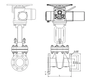
9. Connecting Dimensions
10. Parameters
11. Outline Dimensions
12. Electrical Schematic Diagram & Typical Wire Connection Drawing
13. Intelligent Terminal Connection Drawing
14. Commissioning Instructions for Non-invasive Control Unit
15. Failure and Troubleshooting Methods
General Description
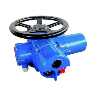
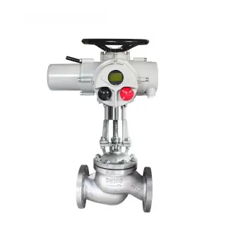
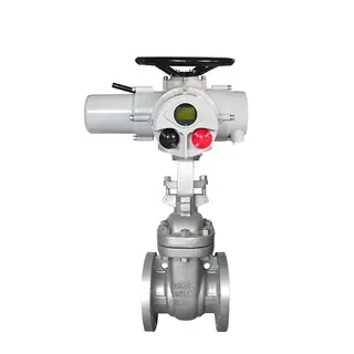
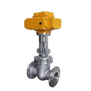
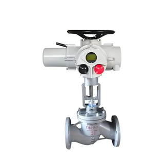
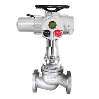
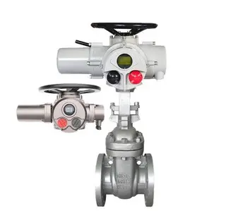
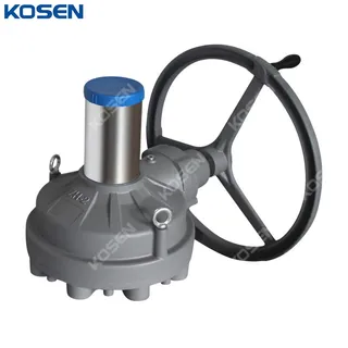
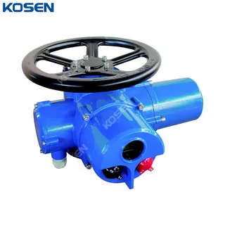
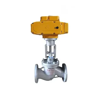
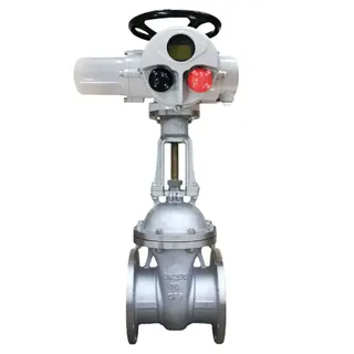
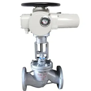
The Z series multi-turn valve electric actuator is suitable for use with gate valves, globe valves, throttle valves, diaphragm valves, and other types of multi-turn valves. Its derived products can also be adapted for use with ball valves, butterfly valves, and air dampers, which are partial rotation valves. This actuator is used for opening, closing, or adjusting valve positions.
As a reliable and steady multi-turn electric actuator, it is applicable in various control systems across different working environments. The actuator is designed with an integrated transmission system, making it compact and with a streamlined appearance. It also features a safe and reliable manual operation design, along with a fully automatic switch between manual and electric modes using a hand shank.
With a high protection class, this actuator is suitable for various designs, including standard type, explosion-proof type, integral switching type, and integral regulation type.
The Z series multi-turn valve electric actuator fully complies with the specifications outlined in GB/T 24923-2010, the Technical Specifications for Basic Version Electric Valve Actuators. Its explosion-proof version meets the requirements of GB 3836.1-2010 (Explosive Atmospheres - Part 1: Equipment - General Requirements), GB 3836.2-2010 (Explosive Atmospheres - Part 2: Equipment Protection by Flameproof Enclosures "d") and GB/T 24922-2010 (Technical Specifications of Explosion-proof Version Electric Valve Actuators).
Designation of Type
W: Outdoor type
Z: Integral type
T: Regulation type
N: Intelligent type
Output rotation speed is designated by a number (rpm).
Connection Type:
T for thrust type
I for power plant type
Normal type has no designation
Rated Torque: Designated by a number (kgf·m).
Product Type: Multi-turn electric actuator
Example: Z10-24/N:Stands for intelligent switching type multi-turns electric device,the rated output torque is 100N·m(10kgf'm),the rated output shaft rotation speed is 24r/min, the rated voltage is 380V.
Working Environment and Main Technical Parameter
1. Power Supply: Rated voltage: 3-phase AC 380V (For special orders, we can provide single-phase 220V, 3-phase 440V, 660V, etc.)
2. IP Protection Class: IP65/67 (For special orders, IP68 is available.)
3. Insulation Class: Class F
4. Ambient Temperature: -20°C to +60°C (For special orders, -40°C to +70°C)
5. Relative Humidity: ≤95% (at 25°C
6. Working Time Duration: Short time: 10 minutes (For special orders, durations of 15–30 minutes are available.)
7. Explosion-Proof: Exd II BT4, suitable for T1-T4 explosive atmospheres, with environments of IIA and IIB class.
8. Working Environment: Regular type, suitable for non-flammable, non-explosive, and non-strongly corrosive environments.
9. Coating: High-temperature stoving varnish.
Installation and Disassembly
The valve electric device can be installed in any position, but it is important to ensure that the motor is positioned as horizontally as possible. The recommended installation method is to place the electric cabinet cap in a horizontal position or with the cap facing vertically upward. This positioning is beneficial for grease application, commissioning, maintenance, and manual operation.
Matters to Be Attention to While Connecting Wires
Use the handwheel to open the valve to 50% of its opening. Press the "Open" or "Close" valve button and check the rotation direction of the valve. If the direction does not match the button’s intended action, immediately press the stop button. Cut off the 3-phase power supply and interchange any two phases of the 3-phase power supply to correct the direction.
Adjustment of Torque Control Device
1. Regular Type
Torque Control Device (as shown in the picture below): The torque control device consists of a crank, block, cam index plate, supporting plates, and a micro switch. When the output shaft is resisted by a certain torque, the worm will rotate and also undergo axial displacement. This displacement will cause the crank to rotate and create an angular shift on the block. The block moves closer to the cam, causing the supporting plates to move upwards. When the torque on the output shaft reaches a preset value, the supporting plates will activate the micro switch, cutting off the power supply and stopping the motor. This controls the output torque of the electric device.
Adjustment of the Torque Control Device: To adjust the off torque, start with a small torque value and gradually increase it until the valve is fully closed. The adjustment of the open/close direction follows after.
Adjustment of Travel Control Device
1. Travel Control Device (Refer to Picture 2)
The travel control device consists of a decimal gear, mandril, cam, and micro switch, and can be referred to as the "counter". Its working mechanism involves the drive pinion (Z = 8) inside the reduction gearbox, which drives the counter. When the counter is adjusted to the valve’s open or close position, the counter rotates to the preset position (turns). Upon reaching this position, the cam will rotate 90°, press on the micro switch, and activate it, cutting off the power supply and stopping the motor. This controls the travel (turns) of the electric device. For valves with many turns, the cam can be rotated 180° or 270° to press the micro switch and stop the motor.
2. Adjustment of Travel Control Device
To adjust the travel control device, follow these steps:
Shut off the valve completely.
Disengage the travel control device by using a screwdriver to rotate the mandril 90°, which will disengage the drive pinion from the digit pinion of the counter.
Rotate the "close" direction adjusting spindle in the arrow direction until the cam presses against the spring-bearing plate and activates the micro switch. This completes the preliminary adjustment for the "close" direction.
Release the mandril to re-engage the drive pinion with the digit pinions on both sides. Slightly rotate the adjusting spindle left and right with a screwdriver to ensure proper engagement.
Test the valve by opening and closing it electrically for several turns to check if the "close" direction travel is satisfactory. If not, repeat the adjustment process.
For the "open" direction adjustment:
After adjusting the "close" direction, manually open the valve to the required position. Note: The travel control device must not be disengaged during this process, as it would cause the "close" direction adjustment to be lost.
Disengage the travel control device and rotate the "open" direction adjusting spindle in the arrow direction until the cam presses against the spring-bearing plate and activates the micro switch.
Re-engage the travel control device and the drive pinion. This completes the "open" direction adjustment.
After adjustment, check the valve’s travel function by operating it electrically several times. Typically, the valve open control is set to around 90%.
3. Adjustable Open Position Indicator (Picture 3)
The adjustable open position indicator consists of reduction gears, adjusting pinion, valve open position scale, cam, micro switch, and potentiometer. During site adjustment, set the gear to the required position based on the number of turns needed for the corresponding valve, and engage it with the gear in the reduction gearbox. The number of turns is indicated on the column. As the valve opens or closes, the open position scale will show the valve’s open position. This indicator ensures that the open position is synchronized with the valve's opening extent, allowing for long-range transmission of the valve position.
4. Manual-Electric Mode Switch Device (Picture 4)
The manual-electric mode switch device is a half-automatic switch. To switch from electric mode to manual mode, the changing shank must be pulled. To switch from manual mode to electric mode, no action is needed, as the switch occurs automatically.
When switching from electric mode to manual mode, pulling the switching shank moves the middle clutch of the output shaft upward, pressing on the spring. As the shank is pulled to a certain position, the middle clutch disengages from the worm gear and engages with the manual shaft jaw. This transmits the force from the handwheel to the output shaft via the middle clutch, enabling manual operation.
When switching from manual mode to electric mode, the motor's rotation causes the worm gear to rotate, causing the up-tight rod to fall immediately. The spring force moves the middle clutch quickly toward the worm gear, disengaging from the manual shaft and re-engaging with the worm gear, thereby switching to electric mode.
Adjustment of Intelligent Travel Control Device
Rotate the mode button (red button) to the "Site" position. Use the handwheel to move the valve to the full stop position. Once reached, rotate the handwheel backward by two full circles.
Use the infrared setting tool to log into the main menu and select "Basic Setting".
Use the "Up" or "Down" button to select "Close Position Setting" and press "Confirm" to save the close position value.
Next, use the handwheel to move the valve to the full open position. Once reached, rotate the handwheel backward by two full circles.
Enter the main menu and select "Open Position Setting". Press "Confirm" to save the open position value.
Log off to complete the process.
Instructions for Commissioning of Non-Invasive Control Unit
Part 1: Operation Instructions
(1) Button Operation Instructions
The red button is the mode button, which switches between "Site", "Stop", and "Distant" modes. It can also be used to save the menu (from "Stop" to "Site") or log out (from "Stop" to "Distant").
The black button is the operation button. In "Site" mode, it can start or stop the operation. In "Setting" mode, it allows for adjustment of values.
While in "Site" mode, short presses activate the site inching mode. If the operation exceeds 3 seconds, the alarm will display "BC", indicating that the valve has entered the field holding mode. To stop movement, either reverse the operation or switch the mode button to "Stop".
(2) Remote Control Operation Instructions
(Note: The remote control is optional; please specify when ordering.)
In "Site" mode, pressing the "Open" button activates the valve to open in holding mode.
Pressing the "Close" button activates the valve to close in holding mode.
Pressing the "Stop" button halts movement.
In "Site" mode, pressing the "Up" button three times consecutively will enter the open position calibration status. The "Open", "Close", and "Stop" buttons will control the electric actuator to open, close, and stop the valve, respectively. Press the "Enter" button to save the travel position. Press "Stop" to exit.
In "Site" mode, pressing the "Down" button three times consecutively will enter the close position calibration status. The operation is the same as above for saving or exiting the status.
Part 2: Signal Finding
(The signal finding area is located in the left bottom area of the screen)
(1) Remote Signal Finding
Switch the mode button to "Distant". The left bottom area of the screen will display the remote control signal received.
Switching Types:
"OP" stands for remote open.
"GL" stands for remote close.
"BC" stands for remote holding.
If multiple statuses coexist, the signals will alternate on the display.
Regulation Type: Displays the control circuit's voltage value received.
(2) Valve Position Signal Finding
Switch the mode button to "Site". The left bottom area of the screen will display the valve position signal.
If the valve position detector is a potentiometer, it will show the percentage of resistance (d01-d99).
If the valve position detector is a 12-digit encoder, it will show the percentage of the encoder (b00-b99).
If the valve position detector is an 18-digit encoder, it will show the permillage of the encoder (000-999).
Part 3: Travel Calibration
Note: Ensure the rotation direction of the electric actuator and the wiring connection of the torque are correct. Also, calibrate the potentiometer or encoder’s rotation range.
(1) Close Position Calibration
At the stop position, rotate the operation button to "Close" for about 3 seconds. Wait until the letter "L" starts flickering, then release the operation button and switch the mode button to "Site".
The letter "L" should stop flickering, indicating that the close position calibration status has been entered.
The operation button can be used to achieve electric open or electric close actions. When the valve reaches the close position, switch the mode button to "Stop", then to "Site".
The red light and letter "L" will flicker twice, outputting a 4mA feedback current, and display 0%, signifying that the close position calibration is complete.
If the mode button is switched from "Stop" to "Distant", the travel calibration will end directly.
(2) Open Position Calibration
At the stop position, rotate the operation button to "Open" for about 3 seconds. Wait until the letter "H" starts flickering, then release the operation button and switch the mode button to "Site".
The letter "H" should stop flickering, indicating that the open position calibration status has been entered.
The operation button can be used to achieve electric open or electric close actions. When the valve reaches the open position, switch the mode button to "Stop", then to "Site".
The green light and letter "H" will flicker twice, outputting a 20mA feedback current, and display 100%, signifying that the open position calibration is complete.
If the mode button is switched from "Stop" to "Distant", the travel calibration will end directly.
Part 4: Output Current Micro-Adjusting
(1) 4mA Output Current Micro-Adjusting
At the stop position, rotate the operation button to "Close" for about 10 seconds. Wait until the letter "LF" flickers, then release the operation button.
Switch the mode button to "Site" and then to "Stop" to enter the 4mA output current micro-adjusting status.
At this point, the output current value can be adjusted by turning the operation button. Adjust the output current to 4mA.
Switch the mode button back to "Site". The red light will flicker 3 times, indicating that the 4mA output current micro-adjusting is complete.
If the mode button is switched from "Stop" to "Distant," the micro-adjusting will end immediately.
(2) 20mA Output Current Micro-Adjusting
At the stop position, rotate the operation button to "Open" for about 10 seconds. Wait until the letter "HF" flickers, then release the operation button.
Switch the mode button to "Site" and then to "Stop" to enter the 20mA output current micro-adjusting status.
At this point, the output current value can be adjusted by turning the operation button. Adjust the output current to 20mA.
Switch the mode button back to "Site". The green light will flicker 3 times, indicating that the 20mA output current micro-adjusting is complete.
If the mode button is switched from "Stop" to "Distant," the micro-adjusting will end immediately.
Part 5: Dead Zone Setting
This function is only applicable for regulation types.
The dead zone is self-adjusting and does not require manual setting.
The accuracy is higher, and there is no vibration.
Part 6: Advanced Setting
Note: During advanced settings, the power should be off. The mode button should be in the "Stop" position. The red light (close position), green light (open position), close position button, and open position button should all be connected to the circuit board.
(1) Loss of Signal Position
This setting is only available for regulation types. The default setting is "Fail in Place".
Press the close position button and power on for about 3 seconds. Release the button when the red light shines for the first time. The red light will flicker 3 times, and the loss of signal will be set to "Fail to the Close Position".
Press the open position button and power on for about 3 seconds. Release the button when the green light shines for the first time. The green light will flicker 3 times, and the loss of signal will be set to "Fail to the Open Position".
Press both buttons and power on for about 3 seconds. Release both buttons when both lights shine. Both lights will flicker 3 times, and the loss of signal will be set to "Fail in Place".
(2) Calibration of Control Current
This setting is only available for regulation types.
Engage the spring bearer plate and ensure the micro switch responds. Then, engage the travel device and the drive pinion. The "Open" direction travel adjustment is now finished. After adjusting the travel control device, the valve can be operated several times. Typically, the valve open control is set to approximately 90%.
Control Current Settings:
Press the close position button and power on for about 10 seconds. Release the button when the red light shines for the second time. The red light will flicker 3 times, and the setting will be "Close with Signal, Open without Signal".
Press the close position button and power on for about 10 seconds. Release the button when the green light shines for the second time. The green light will flicker 3 times, and the setting will be "Open with Signal, Close without Signal".
Press both buttons and power on for about 10 seconds. Release both buttons when both lights shine for the second time. Both lights will flicker 3 times, and the setting will be "Regular Control".
Send your message to this supplier
Related Articles from the Supplier
Related Articles from China Manufacturers

Related Products Mentioned in the Article

Zhejiang Kosen Valve Co., Ltd.
- https://www.kosenvalve.com/
- Business Type: Industry & Trading, Manufacturer,
Supplier Website
Source: https://www.kosenvalve.com/multi-turn-valve-electric-actuator-operating-instruction.html