Erosion Behavior of V-Type Control Ball Valves in Coal Chemical Systems (Part Two)
2. Flow Field Simulation Analysis
2.1 Flow Field Simulation Calculation Theory
1) Turbulence Model
Due to the complex internal flow path of the V-type ball valve and the large pressure gradient at the V-port throttling point, the Realizable turbulence model was selected to ensure calculation stability. Based on the law of conservation of momentum, the governing equations for the Realizable turbulence model are as follows:
Turbulent kinetic energy equation:
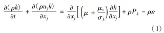
Turbulent kinetic energy dissipation rate equation:
Where:
ρ — fluid density
Pk — turbulent kinetic energy generation term
νt — eddy viscosity coefficient
t — time
uj — component of the velocity vector in the jjj-direction
xj — spatial coordinate in the jjj-direction
μ — dynamic viscosity
∂ — partial derivative operator
The empirical constants are: k=1, σk=1.2, Cμ=1.44, and G=1.92.
2) Discrete Phase Model
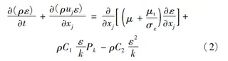
The built-in DPM (Discrete Phase Model) in ANSYS Fluent is widely used to simulate particle-induced erosion. This model accounts for mass and energy exchange between the continuous phase and the discrete phase. The fluid in the continuous phase is solved using the Eulerian approach, while the dispersed phase is tracked using the Lagrangian method. The trajectory of the dispersed phase is obtained by coupling the two phases. The model is expressed as follows:
Where:
v⃗p — particle velocity
v⃗ — fluid velocity
Fd — drag force per unit particle mass
ρp — particle density
Other forces include fluid dynamic viscosity, gravity (g), etc.
Re — particle Reynolds number
Cd — drag coefficient
d — particle diameter
ρ — fluid density
3) Erosion Model
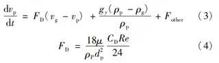
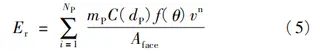
Based on the coupling of multiphase flow in the valve and the turbulent kinetic energy of the fluid, the erosion rate is calculated as follows:
Where:
E — erosion rate (kg/(m²·s))
NP — number of particles impacting a unit area
m˙p — mass flow rate of particles on the effective cross-section (kg/s)
C(dp) — particle size function
fθ — impact angle function
vp — particle impact velocity (m/s)
Aw — wall area of the calculation unit
2.2 Flow Characteristics of the V-Type Ball Valve
To understand the flow behavior of the V-type ball valve under blackwater conditions, the flow coefficient (VVV) was calculated in accordance with GB/T 30832-2014, “Test Method for Valve Flow Coefficient and Flow Resistance Coefficient.” The resulting flow characteristic curve of the V-type ball valve is shown in Figure 5.
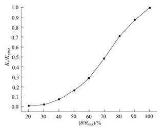
Figure 5. V-type ball valve flow characteristic curve
Figure 5 shows that the V-type ball valve exhibits an approximately equal-percentage flow characteristic, indicating that it provides effective flow control in blackwater media.
2.3 Flow Field Results Analysis
To clearly examine the flow and velocity distribution within the valve, the central cross-section of the V-type ball valve’s fluid domain was chosen as the reference surface for the contour maps. The velocity distribution at a representative valve opening is shown in Figure 6. Figure 6 shows that the flow velocity upstream of the V-type ball valve is relatively uniform, with only a small gradient. However, significant velocity gradients appear at the throttling point between the ball and the front seat, as well as at the diffuser hole in the rear seat, creating localized high-speed regions. At small openings, the effective flow area is limited, causing the fluid’s pressure energy to convert into kinetic energy. This results in a sharp increase in flow velocity and the formation of a localized high-speed jet at the V-shaped opening of the ball. As the valve opening gradually increases, the V-shaped port enlarges, and the high-speed flow regions at the valve opening and backseat extend into the ball’s internal flow channel, forming a high-speed belt that penetrates the sphere. At 40% and 50% openings, a localized jet also forms in the gap between the ball and the valve body. When the valve is fully open (100%), the high-speed zone reaches its maximum extent, extending all the way to the valve outlet and downstream pipeline. Comparison of the maximum flow velocities at different openings shows that as the valve opening increases, the flow resistance at the V-shaped throttling point decreases, leading to reduced pressure losses and lower turbulent kinetic energy dissipation. Consequently, the maximum flow velocity in the fluid domain gradually increases, rising from 22.2 m/s at 40% opening to 35.8 m/s at 100% opening.
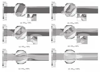
Figure 6. Velocity distribution cloud diagram of the axially symmetrical surface of the V-type regulating ball valve
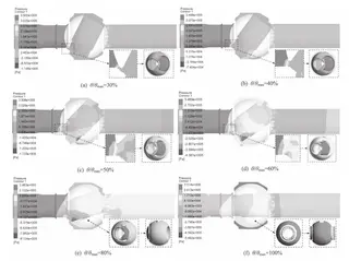
Figure 7. Pressure distribution cloud diagram of the axially symmetrical surface of the V-type regulating ball valve
Figure 7 shows the pressure distribution on the central cross-section of the fluid domain. The pressure patterns within the valve are similar at different openings, with maximum pressure upstream and lower pressure downstream. The regions with the highest pressure gradients are located at the inlet and outlet of the ball. As the fluid passes through the restricted area formed by the ball and the front seat, the flow area abruptly decreases, flow resistance rises, and a significant pressure drop occurs, resulting in negative pressure at the V-port. At 30% opening, the minimum pressure at the V-port reaches -0.11 MPa, well below the saturated vapor pressure of blackwater at 170 °C (0.7926 MPa), creating favorable conditions for cavitation. As the valve opening increases, the flow area expands, and the negative pressure region gradually extends from the tapered portion of the V-port to its straight edge, with the negative pressure reaching -0.91 MPa at 80% opening.
Additionally, at small openings, a minor negative pressure region exists between the diffuser hole in the rear seat and the arched notch of the ball, which is also susceptible to cavitation. Furthermore, the high-speed jet passing through the V-shaped throttling point impacts the ball’s internal flow channel, forming a distinct bull’s-eye-shaped high-pressure region on the channel surface with a pronounced pressure gradient. This high-pressure region expands as the valve opening increases. Since the blackwater medium contains coal ash particles, these solids are carried by the high-speed jet and collide with the bull’s-eye-shaped high-pressure region, leading to erosion wear on the ball.
3. Valve Erosion Simulation Analysis and Verification
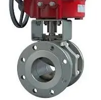
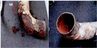
To investigate the erosion characteristics of a V-type regulating ball valve operating in blackwater, a valve that had failed due to wear in a coal chemical process pipeline was disassembled and examined. Figure 8 shows the V-type regulating ball valve and a comparison between the simulated and actual erosion morphologies. The simulation results closely correspond to the actual erosion observed in the field. Severe erosion primarily occurs at the V-shaped throttling area of the front seat, the internal flow path of the ball, the diffuser hole on the rear seat, and the valve body flow path. This agreement confirms the validity of the simulation parameters and the reliability of the numerical model. To further examine the effect of valve opening on erosion wear, additional numerical simulations were performed to characterize erosion at typical valve openings and to analyze the causes of wear in various valve components.
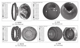
Figure 8. Simulated and actual erosion morphologies of a V-type regulating ball valve
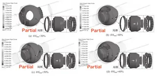
Figure 9. Erosion wear distribution cloud chart for a typical V-type regulating ball valve opening
Figure 9 shows the erosion distribution for a typical valve opening. Severe wear is concentrated at the valve front seat, the flow-facing surface of the ball’s internal channel, the valve body, and the valve rear seat. At 30% opening, erosion is primarily observed on the valve front seat. This is because the small opening creates a large angle between the axis of the ball’s internal flow channel and the pipeline axis, resulting in a reduced flow area at the valve inlet. Due to flow inertia, particles are less likely to change their trajectories and directly impact the front seat, resulting in a maximum erosion rate of 2.2 × 10⁻⁵ kg/(m²·s). As the valve opening increases, a high-speed jet develops within the ball’s internal flow channel. Particles accelerated by the jet’s drag force gain greater kinetic energy, resulting in more particles entering the V-shaped valve and impacting its surfaces. The relationship between erosion rate and relative valve opening was analyzed, with the maximum and average erosion rates for typical openings extracted and plotted in Figure 10.
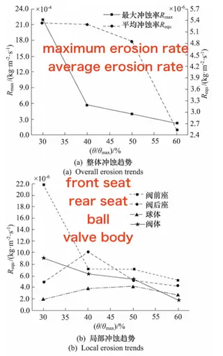
Figure 10. Relationship between erosion wear rate of V-type regulating ball valve and valve opening
(a) Overall erosion trends (b) Local erosion trends
Figure 10a shows that the maximum erosion rate on the valve surface decreases as the valve opening increases, with a particularly sharp decline observed at 40% opening. The average erosion rate also decreases with increasing valve opening, but at a more gradual pace. At small openings, the V-shaped flow area is limited, and particles, due to inertia, poorly follow the fluid flow and directly impact the valve seat at high velocity, resulting in severe wear. As the valve opens further, particles are carried through the ball toward the rear of the valve by the high-speed fluid jet. The particle concentration on the valve seat decreases, leading to a reduction in the maximum erosion rate. However, the high-speed jet zone expands as the valve opening increases, enlarging the collision area on the ball channel’s incoming surface. Although the intensity of particle impacts decreases, the overall average erosion rate declines more gradually. Figure 10b shows that as the valve opening increases, the erosion rate of the valve front seat and valve body generally decreases, whereas the erosion of the valve rear seat and the ball fluctuates and does not decrease significantly. This behavior occurs because the larger opening increases the flow area, reducing particle deposition on the front seat and thereby decreasing its erosion. At the same time, the increased opening limits fluid and particle flow into the gap between the ball and valve body, which weakens erosion of the valve body.
4. Conclusion
This study focuses on the erosion wear of coal chemical blackwater valves, with the V-type regulating ball valve as the research object. Based on finite element simulations and physical disassembly cases, the flow field characteristics and erosion morphology were analyzed, and the causes of wear were identified. The key conclusions are as follows:
Cavitation Risk at Small Openings: Under small opening conditions, significant negative pressure develops in the V-type ball valve, with values well below the saturated vapor pressure of blackwater at 170 °C. This creates favorable conditions for cavitation, making the valve susceptible to cavitation erosion.
High-Speed Jet Impact: At typical openings, the high-speed jet at the V-port throttling section impacts the inner flow channel of the ball, forming a pronounced bull’s-eye-shaped high-pressure area on the channel surface and generating substantial pressure gradients. Repeated impact from solid particles in the medium causes obvious wear pits in this high-pressure region.
Distribution of Severe Wear: The most severe erosion occurs at the valve front seat, the flow-facing surface of the ball channel, the valve body, and the valve rear seat. The maximum erosion rate on the front seat reaches 2.2 × 10⁻⁵ kg/(m²·s), while the rear seat reaches 5.73 × 10⁻⁵ kg/(m²·s), which can potentially lead to serious sealing failures.
Effect of Valve Opening on Erosion: Both the maximum and average erosion rates of the valve wall decrease as the valve opening increases. When the relative opening exceeds 40%, the wear rate is significantly reduced. To extend service life, the V-type ball valve should avoid prolonged operation at small openings.
Send your message to this supplier
Related Articles from the Supplier

Related Articles from China Manufacturers

Erosion in a Pipe Bend
- Aug 13, 2024


High-Corrosion and Erosion-Resistant Ceramic Valves
- Dec 11, 2024
Related Products Mentioned in the Article
Baltic Valve Co., Ltd.
- https://www.baltic-valve.com/
- Business Type: Trading, Industry & Trading, Manufacturer,
Supplier Website
Source: https://www.baltic-valve.com/erosion-behavior-of-v-type-control-ball-valves-in-coal-chemical-systems-part-two.html