Central Heating Valves: Selection and Maintenance
Abstract: With the rapid development of central heating systems, valves—an essential component—are receiving increasing attention when it comes to selection. This paper aims to explore the principles, influencing factors, specific selection methods, and maintenance practices related to central heating valves.
1. Introduction
Valves are essential components in heating systems, responsible for regulating flow, controlling pressure, and isolating media. Selecting the appropriate valve is therefore critical to ensuring the reliable and efficient operation of the entire heating system. Depending on industrial requirements and operating conditions, various types of valves are available, each designed for specific applications.
2. Valve Types and Applications
2.1 Valve Classification
Valves come in a wide variety of types and can be classified in several ways, including by function, pressure rating, operating temperature, mode of operation, and general application. The most commonly used classification method is based on a combination of working principle, intended function, and structural design. Valves are generally categorized into gate valves, globe (stop) valves, throttle valves, ball valves, butterfly valves, diaphragm valves, plug valves, check valves, safety valves, self-operated pressure regulating valves, steam traps, and others.
2.2 Structural Characteristics and Applications of Common Valves
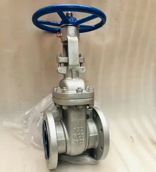
2.2.1 Gate Valves
A gate valve uses a gate, driven by a valve stem, that moves vertically along the sealing surface of the valve seat to open or close the fluid passage. It is primarily used to either connect or completely shut off the flow. The gate valve is composed of a lower valve body, upper bonnet, gate, valve stem, handwheel, sealing ring, and other components.
(1) Gate: It can be classified into wedge-type rigid single gate, wedge-type elastic single gate, wedge-type double gate, and parallel double gate.
(2) Valve Stem: Valve stems are classified into rising stems and non-rising (concealed) stems. A rising stem moves up and down along with the gate during opening and closing, making the valve’s status visible. In contrast, a non-rising stem only rotates to drive the gate up or down, while the stem itself remains stationary in position.
(3) Small-diameter gate valves are typically operated manually, while large-diameter gate valves are often driven by spur gears or electric motors.
Advantages: Low flow resistance, no restriction on flow direction, and short installation length.
Disadvantages: The gate and sealing surfaces are prone to scratching, sealing surface inspection is difficult, and the valve requires a large installation height.
Common Faults and Solutions:
(1) Packing Leakage: Typical solution: tighten the gland or shut off the gas supply to replace the packing.
(2) Oil Cup Leakage: For thread leakage, tighten the oil cup or shut off the gas supply and reinstall it. For leakage at the oil cup opening, apply grease or replace the oil cup.
(3) Handwheel Overtightening: Apply lubricating oil, replace the packing, and clean the valve stem.
(4) Internal Leakage: Drain the system and repair or replace the gate.
Daily Maintenance: Clean the valve, operate the handwheel regularly, drain accumulated fluid, and apply lubricating oil and grease as needed.
2.2.2 Globe Valves and Throttle Valves
Both globe valves and throttle valves are downward-closing valves, with their opening and closing parts (valve discs) driven by the valve stem, moving up and down along the axis of the valve seat (sealing surface).
Structural features of globe and throttle valves: they mainly consist of a valve body, valve bonnet, valve stem, valve disc, and handwheel.
Advantages:
Good sealing performance, minimal friction on the sealing surfaces, easy maintenance, low opening height, and suitable for flow regulation.
Disadvantages:
High flow resistance, long structural length, and large operating force required for opening and closing.
Faults and Treatments:
Packing leakage: Tighten the gland or shut off the gas supply to replace the packing.
Handwheel too tight: Loosen the gland or replace the packing.
Internal leakage: Clean and repair the sealing surface.
Daily Maintenance:
Clean the valve, operate the handwheel regularly, and apply lubricating oil as needed.
2.2.3 Plug Valves
A plug valve has a relatively simple structure, allowing fluid to pass through directly with low pressure drop and enabling quick and convenient opening and closing. The opening and closing component of the plug valve is plug-shaped, and the valve plug connects or disconnects the flow path by rotating 90 degrees relative to the valve body. The plug valve primarily consists of a valve body, a plug, and a packing gland.
Notes:
Straight-through plug valves are mainly used to shut off media flow but can also be used to regulate flow or pressure. Three-way and four-way plug valves are primarily used to change the flow direction or distribute the media. Plug valves can be installed horizontally or vertically, with no restrictions on the flow direction of the media; they can be equipped with electric, hydraulic, or pneumatic actuators for remote or automatic control.
Common Faults and Treatments:
Oil Cup Leakage:
- Leakage at the oil cup thread: tighten the oil cup.
- Leakage at the oil cup opening: apply grease or replace the oil cup.
Handwheel Too Tight:
Apply lubricating oil, vent the valve, disassemble the lower part of the valve body, and adjust the top thread clearance.
Internal Leakage:
Inject sealing grease incrementally and repair the sealing surface.
Daily Maintenance:
Clean the valve, operate the handwheel regularly, and apply lubricating oil and grease as needed.
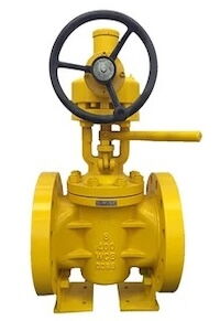
2.2.4 Ball Valves
(1) Manual Ball Valve: The valve disc of a ball valve is a sphere with a hole through its center. The sphere rotates 90 degrees around its axis to open or close the valve. Its performance is similar to that of a plug valve, featuring rapid opening and closing.
Structure of Ball Valve: A ball valve mainly consists of a valve body, a ball, sealing rings, a valve stem, and an actuator.
Features of Ball Valves: Low flow resistance; simple structure and compact size; good sealing performance; easy to operate with quick opening and closing; easy maintenance. However, at high temperatures, they require greater opening and closing torque and may exhibit reduced sealing effectiveness.
Common Faults and Treatments:
External Leakage of the Oil Cup: Leakage at the oil cup thread—tighten the oil cup.
Leakage at the oil cup opening: Apply grease incrementally or replace the oil cup.
Handwheel too tight: Turn the valve screw to reduce the pressure difference across the valve and inspect the worm gear transmission.
Internal leakage: Replace the sealing valve seat and repair the ball.
Daily Maintenance: Clean the valve, operate the handwheel regularly, apply lubricating oil, and inject grease as needed.
(2) Electric Ball Valve: Electric ball valves are used to control and shut off airflow, but they are generally not suitable for flow regulation. Therefore, they should be operated in either a fully open or fully closed position. Ball valves are commonly installed at inlet and outlet stations, pig launching and receiving devices, as well as in certain bypass systems.
Ball valves offer reliable valve seats, automatic pressure relief, fire protection, and well-designed sealing and material selection. They are typically connected using flanged joints and operated by electric actuators.
Common Faults and Treatments:
Oil Cup Leakage:
Leakage at the oil cup thread: tighten the oil cup.
Leakage at the oil cup opening: apply grease or replace the oil cup.
Handwheel Too Tight: Turn the valve screw to adjust.
Internal Leakage and Drainage: Repair or replace the ball.
Daily Maintenance:
Clean the valve, operate (turn) the handwheel, drain any accumulated fluids, apply lubricating oil, and inject grease as needed.
2.2.5 Check Valves
A check valve, also known as a one-way valve, is designed to allow fluid flow in one direction only and prevent backflow. There are two types of check valves: lift type and swing type. The company’s check valve is a swing check valve, whose structural characteristics and working principle are as follows.
(1) Structural Features: It consists of a valve body, valve cover, valve disc, sealing ring, rocker arm, and other components.
(2) Working Principle: When fluid enters the valve from the lower end and the pressure difference across the valve generates a force greater than the weight of the valve disc, the fluid pushes the disc open, causing it to rotate around the rocker arm and allow flow. When the fluid flows back, the outlet pressure exceeds the inlet pressure, causing the valve disc to move in the opposite direction along the rocker due to gravity and pressure difference, thereby preventing backflow.
(3) Precautions: When installing the valve, ensure the inlet and outlet directions are correct so that the valve disc’s flow direction matches the fluid flow.
(4) Common Faults and Treatments: If the valve disc falls off, repair and reinstall it; if the seal is not tight, inspect and replace the sealing ring.
2.2.6 Safety Valves
Safety valves are used on pressure equipment and pipelines in gas transmission stations. When overpressure occurs in the equipment or pipeline, the safety valve automatically opens to release the natural gas and reduce the pressure to a safe level. It consists of a valve body, valve stem, valve disc, valve seat, adjusting screw, spring, and other main components, and is classified into three types: lever type, spring type, and pilot type. The company’s gas transmission station primarily uses spring-type and pilot-type safety valves. Spring-type safety valves are further divided into fully enclosed, semi-enclosed, and open types based on different operating conditions. Based on the valve disc’s opening height, they are classified as fully open and micro-open types. Gas transmission stations primarily use the fully open and fully enclosed types.
Pilot Safety Valve: It consists of a main valve and a pilot (secondary) valve, with both the medium pressure and spring force acting simultaneously on the main valve disc. When overpressure occurs, the pilot valve disc opens first, which then causes the main valve to open; this type is mainly used for large-diameter and high-pressure applications.
3. Principles for Selecting Central Heating Valves
Safety Principle: The valve should have excellent sealing performance to ensure no leakage occurs under harsh conditions such as high pressure and high temperature.
Reliability Principle: The valve should offer a long service life and stable performance to minimize the risk of failure.
Cost-effectiveness Principle: While meeting performance requirements, select valves that offer reasonable prices and high cost-effectiveness.
Maintainability Principle: Valves should be easy to install, disassemble, and repair to minimize future maintenance costs.
4. Factors Affecting the Selection of Central Heating Valves
Medium Characteristics: Different heating media impose varying requirements on valve materials, sealing methods, and other specifications.
Working Pressure and Temperature: The operating pressure and temperature range of the system directly influence valve selection.
Flow and Diameter: The flow rate and pipe diameter of the heating system determine the appropriate valve type and specifications.
Installation Location and Space: The valve’s installation position and space constraints impose specific requirements on its structure and dimensions. When selecting valves for heating stations, both flow rate and pressure must be considered to ensure the stable operation of the heating system.
Generally speaking, pressure and flow are the two primary factors in valve selection. For high-pressure and high-flow media, ball valves or butterfly valves are typically used, while for low-pressure and low-flow media, globe valves, check valves, and other similar types are more suitable. The selection method for central heating valves based on the heating medium is as follows.
(1) Select valve materials based on the characteristics of the medium.
For example, corrosion-resistant materials should be used for corrosive media, while high-temperature–resistant materials are required for high-temperature media. The medium is one of the key factors that determine the appropriate valve type for a heating station. Especially when the medium is corrosive or prone to crystallization, the choice of valve type in the heating station becomes particularly critical.
For media such as oxygen or acids, valves made of corrosion-resistant materials—such as stainless steel—are generally preferred. While for media that tend to crystallize, check valves can be selected to prevent crystallization after the flow stops.
(2) Select the valve rating based on working pressure and temperature. The valve’s pressure and temperature rating should match the operating conditions of the heating system to ensure safe and reliable performance.
(3) Determine valve specifications based on flow and diameter. Calculate the system’s flow and pipe diameter to select the appropriate valve size and type that meet the system’s flow and pressure control requirements.
(4) Consider the installation location and space constraints. When selecting a valve, take into account the installation site and available space, choosing valves with a compact design that are easy to install.
The installation location is an important factor when selecting a valve. Before making a selection, it is necessary to understand the specific conditions of the installation site to avoid unnecessary problems and losses caused by improper choice. For example, when installing valves on straight pipes, non-clogging valves such as ball valves or butterfly valves should be used.
6. Maintenance and Precautions of Valves
As a control component in the hot water flow system, the valve regulates the direction, pressure, and flow rate of the water, making it an indispensable part of heating equipment. To ensure the valve’s reliability and safety, regular maintenance is essential, as it is a meticulous task. If maintenance is neglected, any issue that arises can compromise heating safety and lead to significant economic losses for the heating company. Therefore, proper valve maintenance holds critical importance.
6.1 Importance of Valve Maintenance
(1) Enhance Safety. Valves are crucial components for controlling fluid flow, and their failure can lead to serious safety accidents. Regular maintenance helps detect and repair potential valve issues promptly, thereby reducing safety risks.
(2) Extend Service Life. Proper maintenance can slow the wear of valve components, prolong their service life, and help reduce operational costs for the enterprise.
(3) Ensure Production Efficiency. Issues such as valve blockage or leakage can reduce production efficiency. Regular maintenance keeps valves in good working condition, ensuring smooth and uninterrupted operation.
6.2 Common Methods for Valve Maintenance
6.2.1 Cleaning
Remove dirt and rust from the valve surface to keep it clean. For internal parts, use cleaning agents or compressed air to perform the cleaning. Use saw blades and abrasive cloth to clean the valve body and screws, removing all dust and rust from the bolts of each valve and flange. This ensures the valve body remains clean and free of dust and stains, preventing foreign objects from causing damage or stress during normal operation.
6.2.2 Lubrication
Apply lubricant to the valve’s key moving parts to reduce wear and friction. Use the appropriate lubricating oil and follow the recommended lubrication schedule. Based on operation records, replace the packing and sealing ring if there is running, bubbling, dripping, or leakage. Then, turn the handwheel to retract the valve stem, and apply grease or lubricant to maintain the valve stem.
Bolts and Nuts Maintenance:
Bolts and nuts should be lubricated with oil. This is especially important for valves that are infrequently used—apply oil thoroughly and allow it to sit for a while to prevent rust and ensure smooth operation. Allow the applied grease to penetrate into the valve body for proper lubrication before moving on to the next task.
Apply grease or lubricating oil: The steps for applying grease or lubricating oil must be strictly followed according to the technical specifications for valve maintenance to ensure proper upkeep and smooth operation of the valve.
6.2.3 Adjustment
Check the tightness of all valve components and promptly tighten any loose parts. For regulating valves, regularly inspect their adjustment performance to ensure accurate control.
6.2.4 Replacement
Severely worn or damaged valve parts should be replaced promptly to ensure the valve operates normally.
6.2.5 Verification
Safety-related valves, such as safety valves and pressure-reducing valves, must undergo regular pressure testing to ensure proper operation at the designated pressure.
6.2.6 Sealing Protection
After maintenance, the operator seals the valve with plastic wrap for protection. This practical measure, inspired by everyday experience and adapted to the production process, effectively helps preserve the valve’s condition.
Using plastic wrap to protect the valve not only slows down the oxidation process but also ensures a tight seal, thereby extending the valve’s service life. After completing these steps, the valve maintenance is finished, and the valve can be stored until the next heating season.
6.3 Precautions for Valve Maintenance
(1) Make a plan. Develop a reasonable maintenance schedule based on the valve’s usage frequency, working environment, and other factors, and ensure it is followed accordingly.
(2) Train personnel. Provide professional training for valve maintenance staff to ensure they master the correct operating procedures and maintenance skills.
(3) Use appropriate tools. Use the correct tools for valve maintenance to prevent damage caused by improper equipment.
(4) Pay attention to safety. Follow safety operating procedures during valve maintenance to ensure the safety of both personnel and equipment.
(5) Keep records. Maintain detailed records of valve maintenance and establish archives to facilitate traceability and management.
In short, valve maintenance is essential for ensuring production safety, improving efficiency, and extending the service life of valves.
Regular cleaning, lubrication, adjustment, replacement, and calibration ensure valves remain in good working condition, providing a strong guarantee for the efficient operation of the enterprise.
7. Conclusion
The selection of central heating valves is a crucial aspect of heating system design, as it directly impacts the system’s operational efficiency and safety. During the selection process, it is essential to comprehensively consider factors such as medium characteristics, working pressure and temperature, flow and diameter, installation location, and space constraints, while adhering to the principles of safety, reliability, economy, and maintainability to choose the most suitable valve products. By applying scientific selection methods, the heating system’s normal operation, high efficiency, and energy savings can be ensured. When purchasing heating station valves, quality and reliability must be key considerations. Research the manufacturer’s history and reputation beforehand, and choose valves that comply with relevant national standards to ensure their reliability and durability.
Send your message to this supplier
Related Articles from the Supplier
Central Heating Valves: Selection and Maintenance
- Jun 26, 2025
Related Articles from China Manufacturers

Zhangjiakou Promotes Central Heating Project
- Jun 21, 2014

Central Africa Countries Passed the White Paper
- Oct 24, 2014
Central Asia Pipeline Carried 80 Billion M³ Gas
- Jun 09, 2014


Related Products Mentioned in the Article


-320x320.webp)
Baltic Valve Co., Ltd.
- https://www.baltic-valve.com/
- Business Type: Trading, Industry & Trading, Manufacturer,
Supplier Website
Source: https://www.baltic-valve.com/central-heating-valves-selection-and-maintenance.html