ZHEJIANG VERVO VALVE CO., LTD
Diseño de Válvulas de Tapón en la Unidad de Alquilación de Refinería
Aug 03, 2023
Teresa
On this page
I.Introducción
El ácido cianofluórico catalizador en la unidad de alquilación es altamente tóxico y corrosivo y tiene requisitos extremadamente estrictos en los procesos, equipos y materias primas. El dispositivo es seguro ya largo plazo, y es muy difícil de operar. Solo unos pocos conjuntos de dispositivos todavía se fabrican en China debido al alto costo operativo y los beneficios económicos discretos. El ácido fluorhídrico se vaporiza y forma gas a altas temperaturas y presión, lo que es más probable que cause daño al cuerpo humano. Por lo tanto, es muy importante asegurar el sellado y la confiabilidad de cada parte en la unidad de alquilación. Las válvulas de obturador ordinarias están selladas por el contacto directo entre el cuerpo del obturador de metal terminado y el cuerpo de la válvula, por lo que el rendimiento del sellado es deficiente; la fuerza de apertura y cierre es excelente y es fácil de usar. Por lo general, solo se usa para lugares con baja presión (no superior a 1 MPa) y diámetro pequeño (menos de 100 mm). Para ampliar el rango de aplicación deválvulas de tapón, se han desarrollado muchas estructuras nuevas.
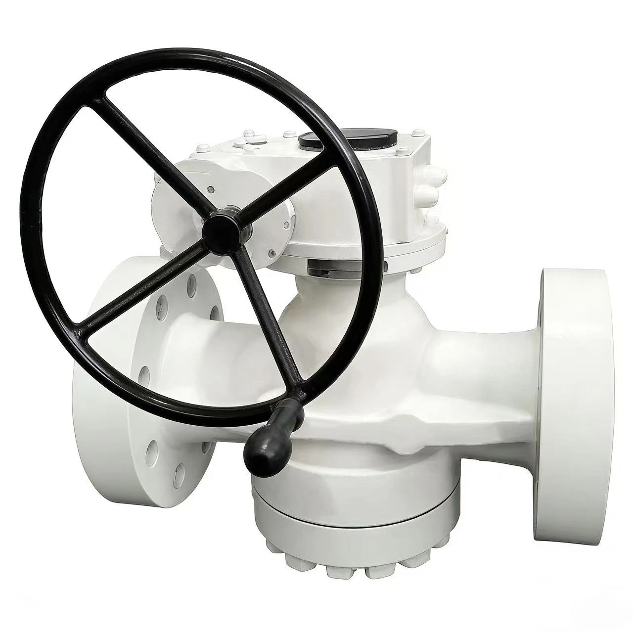
Parámetros de diseño de la válvula de macho (como se muestra en la Figura 1)
Medio: HF y 2,5% de agua
Presión máxima de trabajo: 3.88MPa
Temperatura máxima de funcionamiento: 260°C
Es necesario aumentar la vida útil de la válvula y reducir las fugas de la válvula para garantizar la confiabilidad, la seguridad, la seguridad personal y ambiental.
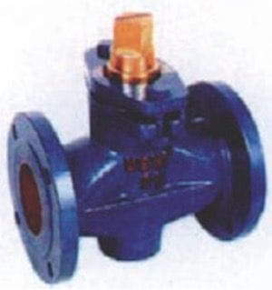
Figura 1 Esquema de la válvula de macho
2.El diseño de la válvula de macho.
Las condiciones de diseño son que el medio sea HF y 2,5 % de agua, presión máxima de trabajo de 3,88 MPa, temperatura máxima de funcionamiento de 260 ℃ y diámetro de la tubería de conexión de 80 mm.
Diseño del canal de enchufe
El ángulo incluido del enchufe suele ser de 4°; si el ángulo incluido es demasiado pequeño, el obturador y el cuerpo de la válvula se atascarán o la rotación del obturador será difícil, como se muestra en la Figura 2. Sin embargo, la literatura determina la conicidad del cono del obturador en proporción. Las principales dimensiones y métodos de cálculo del cuerpo del enchufe se muestran en la Tabla 1.
Tabla 1 Diseño y cálculo de áreas de orificios de canal de gallo
El ácido cianofluórico catalizador en la unidad de alquilación es altamente tóxico y corrosivo y tiene requisitos extremadamente estrictos en los procesos, equipos y materias primas. El dispositivo es seguro ya largo plazo, y es muy difícil de operar. Solo unos pocos conjuntos de dispositivos todavía se fabrican en China debido al alto costo operativo y los beneficios económicos discretos. El ácido fluorhídrico se vaporiza y forma gas a altas temperaturas y presión, lo que es más probable que cause daño al cuerpo humano. Por lo tanto, es muy importante asegurar el sellado y la confiabilidad de cada parte en la unidad de alquilación. Las válvulas de obturador ordinarias están selladas por el contacto directo entre el cuerpo del obturador de metal terminado y el cuerpo de la válvula, por lo que el rendimiento del sellado es deficiente; la fuerza de apertura y cierre es excelente y es fácil de usar. Por lo general, solo se usa para lugares con baja presión (no superior a 1 MPa) y diámetro pequeño (menos de 100 mm). Para ampliar el rango de aplicación deválvulas de tapón, se han desarrollado muchas estructuras nuevas.
Parámetros de diseño de la válvula de macho (como se muestra en la Figura 1)
Medio: HF y 2,5% de agua
Presión máxima de trabajo: 3.88MPa
Temperatura máxima de funcionamiento: 260°C
Es necesario aumentar la vida útil de la válvula y reducir las fugas de la válvula para garantizar la confiabilidad, la seguridad, la seguridad personal y ambiental.
Figura 1 Esquema de la válvula de macho
2.El diseño de la válvula de macho.
Las condiciones de diseño son que el medio sea HF y 2,5 % de agua, presión máxima de trabajo de 3,88 MPa, temperatura máxima de funcionamiento de 260 ℃ y diámetro de la tubería de conexión de 80 mm.
Diseño del canal de enchufe
El ángulo incluido del enchufe suele ser de 4°; si el ángulo incluido es demasiado pequeño, el obturador y el cuerpo de la válvula se atascarán o la rotación del obturador será difícil, como se muestra en la Figura 2. Sin embargo, la literatura determina la conicidad del cono del obturador en proporción. Las principales dimensiones y métodos de cálculo del cuerpo del enchufe se muestran en la Tabla 1.
Tabla 1 Diseño y cálculo de áreas de orificios de canal de gallo
| Serial number | Items | Symbols in the formula | Formula or index | Calculation results |
| 1 | Channel hole area/mm | 5198 | ||
| 2 | Channel hole average width/mm | Wd | 0.57d | 45.6 |
| 3 | Inlet and outlet diameter/mm | d | Take DN (given by design) | 80 |
| 4 | Channel hole length/mm | H | Generally take 2.5 | 114 |
| 5 | The taper of cock body (°) | Generally take 1:6 or 1:7 | 4 |
To reduce the resistance loss and hydraulic loss of the fluid entering the cock, a circular arc is replaced for the channel above the cock hole, and then the edge of the channel is rounded. Although there will be some errors due to the loss of area caused by the rounded corners of the channel, the rounded corners are not drawn in the figure to complicate the geometry; it is considered that the channel area of the plug is the product of Wd and Hd in Figure 2.
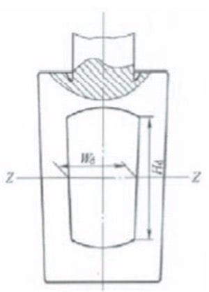
Figure 2 The geometry of the cock
Determination of the main structural dimensions of the valve body
(1) Structure length
The main dimensions of the plug valve body are shown in Figure 3, where L is the structural length of the valve body. Flange ends are adopted due to the relatively large size of the valve. According to the "Valve Design Manual", the structural length of the valve body used in China has certain standards. Here, only the data suitable for the diameter of the designed valve are listed; check Table 2.
Table 2 Structural length of flanged plug valves
| Nominal diameter DN/mm |
Nominal pressure/Pa | |||||
| PN1.0/1.6 (PN2.0/2.5) | PN2.5/4.0 (PN4.0/5.0) | PN10.0 | ||||
| Structural length | ||||||
| Short series | Medium series | Long series | Short series | Long series | ||
| 65 | 100 | 222 | 290 | 241 | 290 | 330 |
| 80 | 203 | 241 | 310 | 283 | 310 | 356 |
| 100 | 229 | 305 | 350 | 305 | 350 | 432 |
Please note that the dimensions shown in bold in the table are preferred. It can be known from the above that the structural length adopted in this design is the short series, namely 283mm.
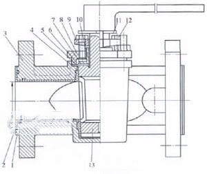
Figure 3 Main dimensions of the valve body
(2) The thickness of the body
For the wall thickness of the valve body, China stipulates the minimum wall thickness (Table 3).
Table 3 Minimum Wall Thickness of Valve Bodies
| Nominal pressure PN/MPa | Nominal diameter DN/mm | ||
| 65 | 80 | 100 | |
| 2.5 | 5.7 | 6.1 | 6.6 |
| 4.0 | 6.2 | 6.7 | 7.3 |
Using the interpolation method, it can be obtained that the minimum wall thickness of the valve body is 6.65mm. Considering the corrosion of HF, the minimum wall thickness is 8mm.
You can also refer to the wall thickness calculation formula recommended in some literature, such as:
tm=1.5pcd/(2S-1.2pc)
In the formula
Tm is the necessary minimum thickness of the valve body, and the unit is inch (1in=25.4mm); pc is nominal pressure, and the unit is psi (1psi=6.895kPa); d is the inner diameter, and the unit is in; S is stress, and S equals to 7000psi.
After converting the units in this article into the units required by the above formula: pc equals to 562.6psi, and d 2.4 inches. tm being 0.101 in can be obtained, which is 2.6mm. Therefore, the 8mm above meets the conditions, and after checking the strength of the valve body, it is found that the thickness still meets the requirement for strength.
(3) Other main dimensions
The other main dimensions of the valve body are also determined by the nominal diameter of the plug valve, and the data are shown in Table 4.
Table 4 Other main dimensions of the valve body (mm)
| Nominal diameters of pipes | 6 | 10 | 12 | 20 | 25 | 30 | 40 | 50 | 60 | 75 | 100 |
| Heights H | 30 | 35 | 38 | 48 | 64 | 70 | 76 | 95 | 108 | 107 | 203 |
| Square head size S | 9.5 | 10 | 11 | 13 | 16 | 18 | 20 | 24 | 30 | 35 | 50 |
| Square head length Q | 11 | 11 | 12 | 14 | 19 | 22 | 24 | 28 | 31 | 35 | 40 |
From Table 4, it can be obtained that H is 142, S 38, and Q 36 by interpolation method.