ZHEJIANG VERVO VALVE CO., LTD
Design of Plug Valves in the Refinery Alkylation Unit
On this page
I. Introduction
The catalyst cyanofluoric acid in the alkylation unit is highly toxic and corrosive and has extremely strict requirements on processes, equipment, and raw materials. The device is safe and long-term, and it is very difficult to operate. Only a few sets of devices are still manufactured in China due to the high operating cost and the inconspicuous economic benefits. Hydrofluoric acid vaporizes and forms gas under high temperatures and pressure, which is more likely to cause harm to the human body. Therefore, it is very important to ensure the sealing and reliability of each part in the alkylation unit. Ordinary plug valves are sealed by the direct contact between the finished metal plug body and the valve body, so the sealing performance is poor; the opening and closing force is great, and it is easy to wear. It is usually only used for places with low pressure (not higher than 1MPa) and small diameter (less than 100mm). To expand the application range of plug valves, many new structures have been developed.
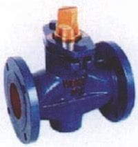
Design parameters of the plug valve (as shown in Figure 1)
Medium: HF and 2.5% of water
Maximum working pressure: 3.88MPa
Maximum operating temperature: 260°C
It is necessary to increase the service life of the valve and reduce the leakage of the valve to ensure reliability, safety, personal and environmental safety.
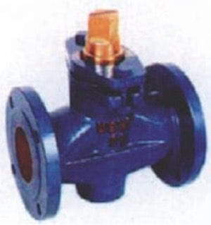
Figure 1 Outline drawing of the plug valve
2. The design of the plug valve
The design conditions are that the medium is HF and 2.5% water, maximum working pressure 3.88MPa, maximum operating temperature 260℃ and connecting pipe diameter 80mm.
Design of the plug channel
The included angle of the plug is usually 4°; if the included angle is too small, either the plug and the valve body will be stuck, or the rotation of the plug will be difficult, as shown in Figure 2. However, literature determines the taper of the plug cone in proportion. The main dimensions and calculation methods of the plug body are shown in Table 1.
Table 1 Design and calculation of cock channel hole areas
The catalyst cyanofluoric acid in the alkylation unit is highly toxic and corrosive and has extremely strict requirements on processes, equipment, and raw materials. The device is safe and long-term, and it is very difficult to operate. Only a few sets of devices are still manufactured in China due to the high operating cost and the inconspicuous economic benefits. Hydrofluoric acid vaporizes and forms gas under high temperatures and pressure, which is more likely to cause harm to the human body. Therefore, it is very important to ensure the sealing and reliability of each part in the alkylation unit. Ordinary plug valves are sealed by the direct contact between the finished metal plug body and the valve body, so the sealing performance is poor; the opening and closing force is great, and it is easy to wear. It is usually only used for places with low pressure (not higher than 1MPa) and small diameter (less than 100mm). To expand the application range of plug valves, many new structures have been developed.
Design parameters of the plug valve (as shown in Figure 1)
Medium: HF and 2.5% of water
Maximum working pressure: 3.88MPa
Maximum operating temperature: 260°C
It is necessary to increase the service life of the valve and reduce the leakage of the valve to ensure reliability, safety, personal and environmental safety.
Figure 1 Outline drawing of the plug valve
2. The design of the plug valve
The design conditions are that the medium is HF and 2.5% water, maximum working pressure 3.88MPa, maximum operating temperature 260℃ and connecting pipe diameter 80mm.
Design of the plug channel
The included angle of the plug is usually 4°; if the included angle is too small, either the plug and the valve body will be stuck, or the rotation of the plug will be difficult, as shown in Figure 2. However, literature determines the taper of the plug cone in proportion. The main dimensions and calculation methods of the plug body are shown in Table 1.
Table 1 Design and calculation of cock channel hole areas
| Serial number | Items | Symbols in the formula | Formula or index | Calculation results |
| 1 | Channel hole area/mm | 5198 | ||
| 2 | Channel hole average width/mm | Wd | 0.57d | 45.6 |
| 3 | Inlet and outlet diameter/mm | d | Take DN (given by design) | 80 |
| 4 | Channel hole length/mm | H | Generally take 2.5 | 114 |
| 5 | The taper of cock body (°) | Generally take 1:6 or 1:7 | 4 |
To reduce the resistance loss and hydraulic loss of the fluid entering the cock, a circular arc is replaced for the channel above the cock hole, and then the edge of the channel is rounded. Although there will be some errors due to the loss of area caused by the rounded corners of the channel, the rounded corners are not drawn in the figure to complicate the geometry; it is considered that the channel area of the plug is the product of Wd and Hd in Figure 2.
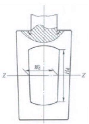
Figure 2 The geometry of the cock
Determination of the main structural dimensions of the valve body
(1) Structure length
The main dimensions of the plug valve body are shown in Figure 3, where L is the structural length of the valve body. Flange ends are adopted due to the relatively large size of the valve. According to the "Valve Design Manual", the structural length of the valve body used in China has certain standards. Here, only the data suitable for the diameter of the designed valve are listed; check Table 2.
Table 2 Structural length of flanged plug valves
| Nominal diameter DN/mm |
Nominal pressure/Pa | |||||
| PN1.0/1.6 (PN2.0/2.5) | PN2.5/4.0 (PN4.0/5.0) | PN10.0 | ||||
| Structural length | ||||||
| Short series | Medium series | Long series | Short series | Long series | ||
| 65 | 100 | 222 | 290 | 241 | 290 | 330 |
| 80 | 203 | 241 | 310 | 283 | 310 | 356 |
| 100 | 229 | 305 | 350 | 305 | 350 | 432 |
Please note that the dimensions shown in bold in the table are preferred. It can be known from the above that the structural length adopted in this design is the short series, namely 283mm.
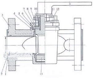
Figure 3 Main dimensions of the valve body
(2) The thickness of the body
For the wall thickness of the valve body, China stipulates the minimum wall thickness (Table 3).
Table 3 Minimum Wall Thickness of Valve Bodies
| Nominal pressure PN/MPa | Nominal diameter DN/mm | ||
| 65 | 80 | 100 | |
| 2.5 | 5.7 | 6.1 | 6.6 |
| 4.0 | 6.2 | 6.7 | 7.3 |
Using the interpolation method, it can be obtained that the minimum wall thickness of the valve body is 6.65mm. Considering the corrosion of HF, the minimum wall thickness is 8mm.
You can also refer to the wall thickness calculation formula recommended in some literature, such as:
tm=1.5pcd/(2S-1.2pc)
In the formula
Tm is the necessary minimum thickness of the valve body, and the unit is inch (1in=25.4mm); pc is nominal pressure, and the unit is psi (1psi=6.895kPa); d is the inner diameter, and the unit is in; S is stress, and S equals to 7000psi.
After converting the units in this article into the units required by the above formula: pc equals to 562.6psi, and d 2.4 inches. tm being 0.101 in can be obtained, which is 2.6mm. Therefore, the 8mm above meets the conditions, and after checking the strength of the valve body, it is found that the thickness still meets the requirement for strength.
(3) Other main dimensions
The other main dimensions of the valve body are also determined by the nominal diameter of the plug valve, and the data are shown in Table 4.
Table 4 Other main dimensions of the valve body (mm)
| Nominal diameters of pipes | 6 | 10 | 12 | 20 | 25 | 30 | 40 | 50 | 60 | 75 | 100 |
| Heights H | 30 | 35 | 38 | 48 | 64 | 70 | 76 | 95 | 108 | 107 | 203 |
| Square head size S | 9.5 | 10 | 11 | 13 | 16 | 18 | 20 | 24 | 30 | 35 | 50 |
| Square head length Q | 11 | 11 | 12 | 14 | 19 | 22 | 24 | 28 | 31 | 35 | 40 |
From Table 4, it can be obtained that H is 142, S 38, and Q 36 by interpolation method.