Multi-Station Precision Machining of Ball Valve Spheres
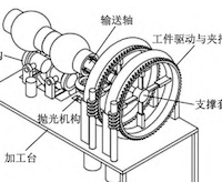
To address the low efficiency, poor machining consistency, and limited automation of conventional discrete machining processes for ball valve spheres, a multi-station continuous precision machining device was developed.
This paper describes the structure of the device and analyzes machining tests performed on a prototype. Compared with conventional discrete machining, the proposed device:
- Reduces the machining cycle time per sphere by 32.5%.
- Keeps the sphericity error below 8 μm.
- Maintains a stable surface roughness (Ra) of approximately 0.18 μm.
This device provides an effective solution for the efficient, consistent, and continuous precision machining of ball valve spheres, demonstrating significant practical value.
Ball valves offer advantages such as low flow resistance, reliable sealing, and rapid opening and closing, making them widely used in industries such as petrochemicals. The sphere is the core component of a ball valve, and its geometric accuracy and surface quality directly affect the overall performance of the valve. Currently, the manufacturing process for ball valve spheres typically includes forging or casting, rough machining, heat treatment, semi-finishing, precision grinding, and polishing, with grinding and polishing having the greatest impact on the final machining quality.
Traditionally, ball valve spheres are machined using a discrete, single-machine, single-part approach, with each sphere requiring independent clamping, centering, and machining on grinding and polishing machines. This traditional machining approach has several significant limitations. First, repeated clamping can introduce positioning errors, which adversely affect machining accuracy and product consistency. Second, the auxiliary time between processes accounts for a significant portion of the total machining time, limiting production efficiency and the potential for capacity expansion. Third, machining quality depends heavily on the operator's skills and experience, resulting in considerable quality variation and making stable mass production difficult.
Research on ball valve technology, both domestically and internationally, has long focused on the development and application of new sealing materials, while relatively little systematic research has been conducted on high-efficiency, high-precision manufacturing equipment for ball valve spheres. While some researchers have explored advanced machining processes for the precision manufacturing of complex curved surfaces, the high cost of such equipment and the lack of validation of process stability and reliability hinder their widespread adoption.
Therefore, developing a specialized device that integrates multiple machining processes to enable the continuous production of ball valve spheres is of significant practical value for engineering applications. To address the bottlenecks in ball valve sphere machining, including discrete processing steps, low efficiency, and poor consistency, a multi-station continuous precision machining device was developed. The device integrates automatic workpiece transfer, precise rotation, high-efficiency grinding, and fine polishing to enable continuous machining of ball valve spheres. This paper presents the design and structure of the device and evaluates its machining performance through prototype testing.
The ball valve sphere is treated as a standardized workpiece in an assembly-line machining process. A central positioning and precision drive system enables the sphere to rotate steadily about its own axis while moving linearly through the machining stations. This arrangement allows multiple fixed-position machining units to sequentially process the entire outer surface of the sphere, enabling efficient, continuous, full-surface machining. The overall architecture of the multi-station continuous precision machining device for ball valve spheres is shown in Figure 1. The device comprises a machining platform, a workpiece transport and support system, a workpiece drive and clamping system, grinding and polishing mechanisms, and a control system. The workpiece transport and support system consists of components such as a transport shaft and a support sleeve.
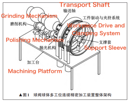
Figure 1. Overall Architecture of the Multi-Station Continuous Precision Machining Device for Ball Valve Spheres
The workpiece transport and support system provides axial feed and high-precision positioning during ball valve sphere machining, both of which are essential for ensuring machining quality and efficiency. The core component of the system is a high-rigidity transport shaft fixed to the machining platform, providing structural stability and sufficient rigidity to withstand machining loads. A support sleeve capable of precise axial sliding is fitted over the transport shaft, and the high-precision fit between the two ensures smooth movement and accurate positioning.
Multiple support rods are evenly distributed around the circumference of the support sleeve, providing balanced and uniform support. The outer end of each set of support rods is connected to a support crossbar through a revolute joint, allowing the crossbar to rotate freely. The ball valve sphere is mounted on the outside of the support sleeve using a transition mandrel or a dedicated fixture, with the sphere's inner bore in contact with the support crossbars to establish a stable load-transfer path.
As shown in Figure 2, the workpiece transport and support system serves two primary functions. First, the circumferentially distributed support rods provide radial positioning for the sphere, constraining its radial degrees of freedom and preventing machining misalignment and vibration. Second, the rotational capability of the support crossbars allows the sphere and support sleeve to move smoothly along the transport shaft under axial thrust, thereby enabling axial feed.
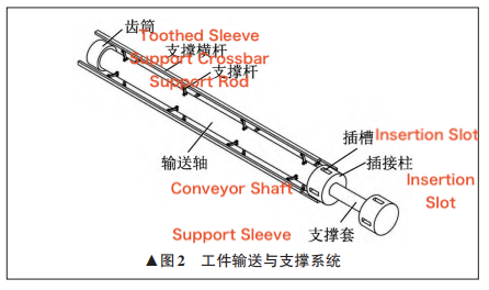
Figure 2. Workpiece transport and support system
The workpiece drive and clamping system consists of a clamping ring, a ring frame, a drive motor, and other components. It enables continuous rotation of the workpiece about its axis, providing the rotational motion required for high-precision grinding and polishing of the ball valve sphere. The drive stations are positioned along the axis of the transport shaft between the grinding and polishing stations, ensuring stable and reliable rotational positioning as the sphere moves through the system.
At the heart of each drive station is a clamping ring capable of continuous 360° rotation. The clamping ring is mounted within a stationary ring frame through high-precision bearings, forming a stable rotary connection. Multiple radially extendable rods are evenly spaced around the inner circumference of the clamping ring. Their ends can engage with sockets on the outer surface of the support sleeve or with fixed slots on the transport shaft. Once the ball valve sphere reaches a machining station, the extendable rods actuate to lock the support sleeve in position. A drive motor mounted on the ring frame drives a gear ring fixed to the side of the clamping ring through a worm gear, causing the clamping ring to rotate and thereby driving the locked support sleeve and sphere to rotate about the same axis.
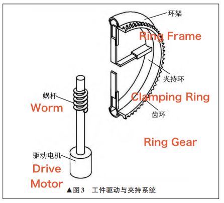
Figure 3. Workpiece drive and clamping system
After machining is complete, the extendable rods retract, and an axial propulsion mechanism moves the sphere to the next station. By alternating the actuation of the telescopic rods in different clamping rings, the system enables a continuous cycle of sphere transfer, positioning, rotational machining, and advancement to the next station.
The grinding and polishing mechanisms are independently installed beside their respective workstations on the machining platform. The grinding mechanism primarily consists of a grinding frame, a grinding motor, and a grinding wheel. The grinding frame is mounted on the grinding guide frame through a sliding connection, allowing it to move back and forth along the guide frame. The grinding motor is mounted on the grinding frame and actuated by a grinding pressure cylinder, with its output shaft directly driving the grinding wheel at high speed. The grinding wheel has an arc-shaped profile designed to match the curvature of the sphere, ensuring full contact with the spherical surface during grinding. The grinding pressure cylinder provides and precisely controls the constant pressure applied by the grinding wheel to the sphere's surface, ensuring grinding stability and consistent machining quality. The grinding mechanism is illustrated in Figure 4.
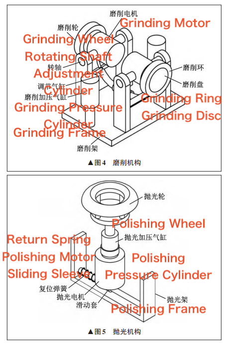
Figure 4. Grinding Mechanism
Figure 5. Polishing Mechanism
The polishing mechanism has a structure similar to that of the grinding mechanism and comprises components such as a polishing frame, a polishing motor, and a polishing wheel. The polishing frame is connected to the polishing guide frame by a return spring, allowing it to automatically return to its initial position after each polishing stroke. The polishing wheel has a concave working surface and is connected to the output shaft of the polishing motor through a polishing pressure cylinder, which enables pressure to be applied and rapidly released during the polishing process. The polishing mechanism is illustrated in Figure 5.
The control system adopts an architecture that combines a programmable logic controller (PLC) with an industrial computer. The PLC manages the sequential control and safety interlocking of actuators, including the drive motors and grinding and polishing pressure cylinders. The industrial computer runs the human-machine interface (HMI) and process parameter management software, enabling the setting and storage of machining parameters for ball valve spheres of various specifications, as well as real-time process monitoring.
The test specimens were made of austenitic stainless steel. A prototype of the multi-station continuous precision machining device for ball valve spheres was used for the machining tests. The spheres had a diameter of 150 mm, with a grinding allowance of 0.3 mm. During grinding, the grinding wheel was operated at a linear speed of 35 m/s, the axial feed rate was set to 100 mm/min, and the sphere rotation speed was 8 r/min. The grinding pressure cylinder was actuated to maintain a normal grinding force of approximately 150 N. During polishing, the sphere rotation speed was set to 15 r/min, the polishing pressure cylinder was actuated to maintain a pressure of approximately 50 N, and the polishing time per sphere was 3 min.
A coordinate measuring machine (CMM) was used to measure the sphericity and diameter of the spheres, while a surface profilometer was used to measure their surface roughness. Ten spheres were machined continuously, with an average cycle time of 31.5 min per sphere, representing a 32.5% reduction in cycle time compared with the traditional discrete machining mode, which required 46.7 min per sphere.
Among the ten machined spheres, the maximum sphericity error was 7.8 μm, with an average of 6.2 μm. The deviation in sphere diameter after machining remained within ±5 μm. After polishing, the surface roughness (Ra) ranged from 0.15 to 0.21 μm, with an average of 0.181 μm and a standard deviation of 0.0170 μm. The surface roughness measurement results are presented in Table 1.
Table 1. Surface roughness measurement results for ball valve spheres
|
No. |
Surface Roughness (μm) |
|
1 |
0.17 |
|
2 |
0.19 |
|
3 |
0.18 |
|
4 |
0.16 |
|
5 |
0.20 |
|
6 |
0.18 |
|
7 |
0.19 |
|
8 |
0.15 |
|
9 |
0.21 |
|
10 |
0.18 |
The primary advantages of the multi-station continuous precision machining system for ball valve spheres are process integration, continuous operation, and machining consistency. By integrating the previously discrete grinding and polishing processes with automated workpiece transfer and station switching, the system enables continuous operation and improves overall equipment utilization. All finishing operations are completed in a single clamping setup, eliminating errors associated with repeated workpiece clamping. Combined with the high-rigidity workpiece transport, support, drive, and clamping systems, this design ensures consistent machining accuracy.
(1) Initial investment and complexity
Compared with traditional standalone machines, the multi-station continuous precision machining system has a more complex mechanical structure and control system, resulting in higher initial investment.
(2) Reliance on process mandrels
The current machining system relies on high-precision process mandrels. Future research could explore direct support and drive technologies that eliminate the need for process mandrels.
(3) In-process inspection and adaptive compensation
Future research will focus on integrating sensors for in-process dimensional measurement and surface quality inspection, enabling adaptive adjustment of machining parameters based on measurement data. This represents an important step toward intelligent machining.
To address the low efficiency and poor consistency associated with traditional discrete machining of ball valve spheres, a multi-station continuous precision machining system was designed. Prototype machining tests demonstrate that the system reduces the machining cycle time per sphere by 32.5% compared with traditional discrete machining, while maintaining a sphericity error of less than 8 μm and a surface roughness (Ra) of approximately 0.18 μm.