Maintaining Underground Pipeline Ball Valve Reliability in Complex Geological Conditions
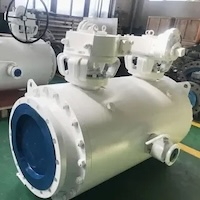
Abstract: To address the poor reliability of underground pipeline networks caused by ball valve failures and the lack of coordination between valve chamber maintenance and ball valve maintenance under complex geological conditions, an integrated, synergistic technology system was developed to ensure the long-term, stable operation of the network. Through field surveys, we identified the key geological constraints, developed strategies for ball valve diagnosis and maintenance, refined valve chamber maintenance protocols, and established a synergistic framework whose effectiveness was verified through experiments and simulations.
The main results are as follows:
- After implementing the synergistic technology, the ball valve failure rate in soft-soil areas dropped to 8.3%, while the valve chamber integrity rate in karst areas rose to 91.5%.
- Simulations revealed a 27.4% reduction in the stress concentration factor at the ball valve sealing surface, along with a maintenance cycle extended by over 40%.
By coordinating ball valve and valve chamber maintenance, this synergistic technology mitigates adverse geological effects, improves pipeline network reliability, and offers a useful reference for similar projects.
Underground pipeline networks are a critical component of urban infrastructure, and their operational stability is essential to the normal functioning of cities. Nearly 60% of Chinese cities are located in regions with complex geological conditions, including soft soil and karst. Such environments can cause ball valve corrosion and seizure, as well as valve chamber leakage and deterioration, thereby threatening the operational safety of the pipeline network. The mechanical reliability of ball valves governs the efficiency of flow control within the network, while the quality of valve chamber maintenance directly affects the service life of the valves. At present, the industry largely relies on a fragmented maintenance model: ball valve maintenance is limited to emergency repairs and lacks geological adaptability, while valve chamber maintenance fails to consider its impact on ball valves. This approach increases maintenance costs and undermines pipeline network reliability. In light of the operating characteristics of ball valves and valve chambers under complex geological conditions, this study develops a reliability-centered maintenance system for ball valves and a corresponding set of maintenance technologies for valve chambers. A coordination mechanism is established and its effectiveness verified, providing a new approach to long-term pipeline network maintenance in complex geological regions.
1 Operational Characteristics of Ball Valves and Valve Chambers in Underground Pipeline Networks under Complex Geological Conditions
Complex geological environments degrade the operational performance of ball valves through coupled physical and chemical processes. In soft soil regions, the soil typically has high void ratios and high water content, along with elevated concentrations of corrosive ions such as Cl⁻ and SO₄²⁻. These ions penetrate the ball valve through gaps in the sealing surface, triggering electrochemical corrosion of the valve core, with the corrosion rate rising exponentially as soil water content increases. The corrosion kinetics equation is expressed as:
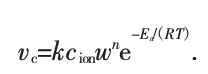
where VC is the corrosion rate of the valve core, in mm/a; k is the corrosion rate constant, in mm·L/(mo l·a); c ion is the concentration of corrosive ions, in mo l/L; w is the soil moisture mass fraction, in %; and n is the moisture influence coefficient, ranging from 1.2 to 1.5. Ea is the activation energy of the corrosion reaction, in kJ/mo l; RR is the gas constant, taken as 8.314 J/(mo l·K); and TT is the absolute temperature, in K. In karst regions, irregular cavities and fissures in the strata make pipeline networks prone to stress concentration during installation. Ball valve bodies are subjected to uneven geostress over the long term, causing the valve stem to bend and the sealing surfaces to fit less precisely—significantly increasing the risk of leakage. In areas with high groundwater levels, groundwater pressure can reach 0.3–0.8 M Pa. Pressurized water seeps through gaps in the valve chamber, which accelerates the aging of the ball valve seat rubber, degrades sealing performance, and causes the valve stem to rust and seize up.
Three representative regions were selected as the study areas: the soft soil region (represented by Shanghai and Tianjin), the southwest karst region (represented by Guiyang and Guilin), and the Pearl River Delta high-groundwater region (represented by Guangzhou and Shenzhen). Using stratified sampling, a total of 102 underground pipeline valve chambers were selected, with service lives of 3–5, 6–10, and 11–15 years. Through on-site inspections, non-destructive testing, and the analysis of operation and maintenance data, the structural and functional issues that arose during the service life of these chambers were systematically analyzed. The statistical results are presented in Table 1.
Table 1 Statistics on Service Issues in Valve Chambers under Complex Geological Conditions
|
Geological Condition |
Service Life (years) |
Structural Cracks (%) |
Leakage (%) |
Anti-Corrosion Coating Failure (%) |
Poor Drainage (%) |
Component Loosening (%) |
|
Soft Soil |
3–5 |
21.4 |
28.6 |
39.3 |
46.4 |
17.9 |
|
6–10 |
35.7 |
46.4 |
57.1 |
67.9 |
28.6 |
|
|
11–15 |
53.6 |
60.7 |
75.0 |
82.1 |
42.9 |
|
|
Karst |
3–5 |
42.9 |
25.0 |
28.6 |
14.3 |
32.1 |
|
6–10 |
64.3 |
39.3 |
46.4 |
21.4 |
46.4 |
|
|
11–15 |
82.1 |
53.6 |
64.3 |
32.1 |
64.3 |
|
|
High-Groundwater |
3–5 |
17.9 |
53.6 |
46.4 |
39.3 |
14.3 |
|
6–10 |
32.1 |
75.0 |
64.3 |
57.1 |
25.0 |
|
|
11–15 |
46.4 |
89.3 |
78.6 |
71.4 |
35.7 |
As shown in Table 1, the incidence of service-related issues in valve chambers under complex geological conditions increases significantly with service duration, and the dominant issues vary with geological conditions.
Soft-soil areas: Poor drainage and anti-corrosion coating failure become particularly prominent with increasing service time. For example, the incidence of poor drainage in valve chambers aged 11–15 years reaches 82.1%, mainly due to drainage slope deformation caused by soft-soil settlement.
Karst areas: Structural cracking is the most severe issue, with an incidence of 82.1% in chambers aged 11–15 years, closely linked to uneven ground settlement and the development of karst cavities.
Areas with high groundwater levels: Leakage issues persist throughout the service life, with an incidence of 89.3% in chambers aged 11–15 years, driven mainly by groundwater pressure.
These issues not only directly threaten the structural integrity of the valve chambers but also exacerbate ball valve malfunctions through mechanisms such as moisture ingress and stress transmission, creating a vicious cycle.
Based on the failure characteristics of ball valves in complex geological environments, a comprehensive diagnostic system integrating ultrasonic testing, magnetic particle testing, and sealing performance testing has been established. Ultrasonic testing uses a 2.25 MHz straight-beam probe to measure the thickness of the valve body and ball and detect internal defects, with a detection depth of up to 50 mm and a defect identification accuracy of 0.2 mm, effectively identifying internal corrosion pits and cracks. Magnetic particle testing targets ferromagnetic components such as the valve stem; using the wet continuous magnetization method, it can detect surface and near-surface microcracks larger than 0.1 mm. In the sealing performance test, compressed air at 0.6 MPa is injected into the ball valve cavity and held for 30 min. Pressure changes are monitored using a pressure sensor, and a leakage rate exceeding 0.05 MPa/h is considered a sealing failure.
The diagnostic process is as follows: first, ultrasonic testing is used to assess the degree of valve body corrosion and detect internal defects; next, magnetic particle testing detects cracks at the connection between the valve stem and valve seat; finally, sealing performance testing verifies sealing reliability. Based on these results, a classification standard for ball valve fault levels is established (see Table 2) to provide a basis for formulating maintenance strategies.
Table 2 Classification Standards for Ball Valve Fault Levels
|
Fault Level |
Corrosion Depth (mm) |
Crack Length (mm) |
Leakage Rate (MPa/h) |
Treatment Method |
|
Level I (Minor) |
≤0.5 |
≤3 |
≤0.02 |
Routine maintenance |
|
Level II (Moderate) |
0.5–1.0 |
3–10 |
0.02–0.05 |
Localized repair |
|
Level III (Severe) |
>1.0 |
>10 |
>0.05 |
Complete replacement |
Differentiated maintenance strategies are formulated based on fault diagnosis results and geological conditions.
Soft soil areas: The focus is on anti-corrosion repair: for valve ball surfaces with a corrosion depth of ≤0.5 mm, plasma spraying is used to apply a Cr₃C₂–Ni Cr coating with a thickness of 0.3–0.5 mm. This coating provides 2.3 times the corrosion resistance of traditional coatings. For components with a corrosion depth >0.5 mm, laser cladding is employed for repair, using Inconel 625 alloy as the cladding material; the hardness of the repaired components reaches 35–40 HRC, meeting service strength requirements.
Karst areas: The focus is on structural correction and stress relief: hydraulic correction is used to straighten bent valve stems, with the correction precision controlled within 0.1 mm/m; Elastic support devices are installed on both sides of the valve body, and stress sensors monitor ground stress changes in real time. When the stress exceeds 250 MPa, a stress-relief mechanism is automatically activated to prevent permanent deformation of the valve body.
Areas with high groundwater levels: The focus is on enhancing sealing performance. Specifically, water-resistant fluororubber seats are used, offering a service life more than three times that of standard rubber seats. In addition, a dual-sealing structure combining V-rings with a labyrinth seal is implemented at the valve stem, with the sealing surface pressure controlled between 0.8 and 1.2 MPa, effectively blocking groundwater ingress.The maintenance decision-making model is based on reliability theory and aims to minimize maintenance costs while maximizing service life. The decision function is defined as follows:
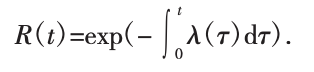
where R(t) is the reliability of the ball valve; λ(т) is the failure rate function; and t is the service time after maintenance, which can be used to determine the optimal maintenance timing through the model.
Differentiated protection technologies are adopted based on geological conditions:
Soft-soil areas: Steel mesh reinforcement combined with polymer grouting is used to inhibit cracking and improve structural integrity.
Karst areas: Enlarged foundations combined with anti-slide piles are used to enhance structural stability.
Areas with high groundwater levels: A cement-based capillary crystalline waterproofing coating combined with sump pits and drainage pumps is used for seepage control and drainage.
For valve chambers in areas with high groundwater levels, the focus is on seepage control and drainage. A cement-based capillary crystalline waterproofing coating is applied to the exterior surfaces of the chamber walls, with a coating thickness of ≥1.5 mm and a permeability coefficient of ≤1×10⁻⁸ m/s. A sump pit and drainage pump are installed at the bottom of the chamber, with a sump pit volume of ≥0.5 m³ and a pump head of ≥15 m. Automatic drainage is activated when the water level in the sump pit exceeds 200 mm, thereby keeping the chamber interior dry.
A maintenance cycle optimization model is established with a valve chamber reliability requirement of ≥ 0.9. The calculation formula is:

where R allow is the minimum allowable reliability, taken as 0.9; λ₀is the failure rate under standard conditions; and K is the geological influence coefficient (1.8 for soft soil areas, 2.2 for karst areas, and 2.5 for high groundwater areas).
The calculated optimal maintenance cycles are 1.5 years for soft soil areas, 1.0 year for karst areas, and 0.8 years for high groundwater areas. Maintenance records incorporating structural inspections, anti-corrosion repairs, and other activities are established to achieve full life-cycle management.
A collaborative logical framework of “condition sensing–decision coordination–execution feedback” is established (see Figure 1) to achieve close integration between ball valve repair and valve chamber maintenance.
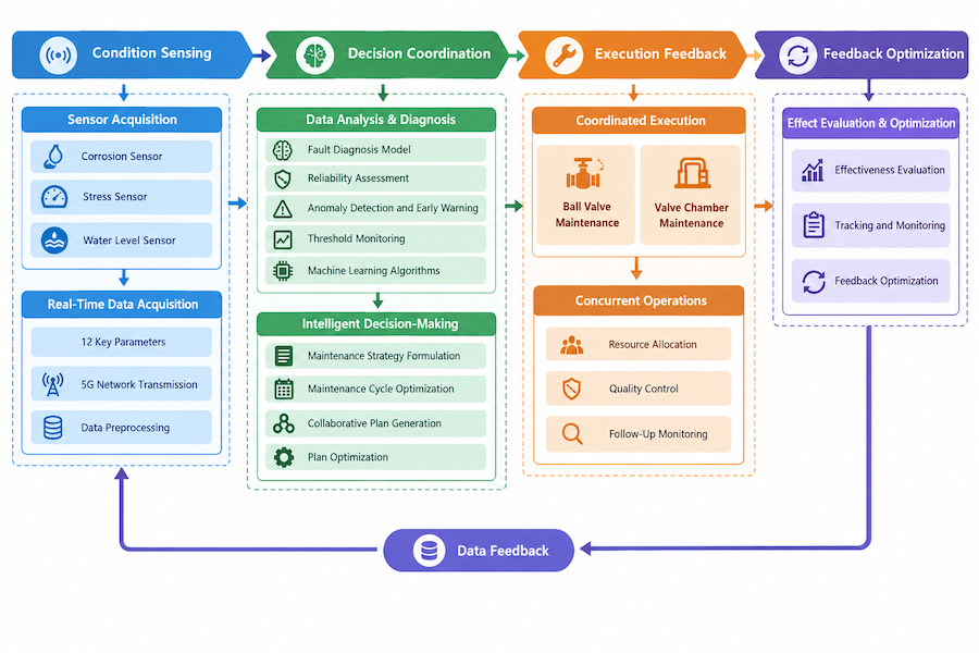
Figure 1 Collaborative Logical Framework for Ball Valve Repair and Valve Chamber Maintenance
The condition sensing layer uses sensors deployed on the ball valves and within the valve chambers, such as corrosion sensors, stress sensors, and water level sensors, to collect 12 key parameters—including corrosion rate, structural stress, and groundwater level—in real time. The decision-making and coordination layer formulates collaborative plans based on parameter monitoring results, integrating fault diagnosis and maintenance cycle models.
Specifically, if a ball valve develops a Grade I or higher fault, the structural condition of the valve chamber is inspected simultaneously. If issues such as leakage or cracks are found, maintenance is performed concurrently. Conversely, if structural deformation is detected during valve chamber maintenance, stress testing and calibration of the ball valve are promptly conducted.
The execution and feedback layer records maintenance data—including locations, measures taken, and material consumption—via data acquisition terminals. This data is fed back to the decision-making layer, where machine learning algorithms continuously optimize the collaborative plans, thereby establishing a closed-loop management system.
The collaborative execution process consists of four stages.
The first stage is condition monitoring, in which sensors collect data every 15 minutes and transmit it over a 5G network to a monitoring platform. The platform then processes the data, detects anomalies, and triggers early warnings whenever parameters exceed preset thresholds.
The second stage is plan formulation, in which technical personnel develop a collaborative maintenance plan by integrating early warning information, geological data, and equipment history, while specifying the scope of work, schedule, and technical requirements.
The third stage is on-site execution, which employs either a “maintenance-before-repair” or a “simultaneous operation” approach. For instance, if leakage in a valve chamber interferes with ball valve repair, anti-seepage treatment is performed on the chamber before the valve is repaired. If space permits, however, ball valve inspection and structural reinforcement of the chamber can be carried out concurrently.
The fourth stage is effectiveness evaluation, in which follow-up monitoring is conducted one, three, and six months after completion to assess the equipment’s operational status and the effectiveness of the collaborative approach, culminating in an evaluation report.
Two valve chambers and their corresponding DN300 ball valves were selected as experimental subjects from each of three areas: soft soil, karst, and high groundwater. These were divided into an experimental group, which used the collaborative technology, and a control group, which used traditional separate maintenance methods, with three sets of equipment in each group and an experimental period of two years. Throughout the experiment, key indicators—including ball valve failure rates, valve chamber structural integrity, and maintenance costs—were monitored.
Experimental materials and equipment: Cr₃C₂–NiCr coating material, Inconel 625 alloy powder, epoxy resin grouting material, and fluororubber valve seats; ultrasonic testing instrument (CTS-9006), magnetic particle flaw detector (CDX-Ⅲ), pressure sensor (CYG1101), and stress sensor (BSG-200).
An ANSYS Workbench coupled simulation model of the ball valve and valve chamber was developed. The model dimensions were based on actual engineering parameters: a ball valve body diameter of 300 mm and a wall thickness of 15 mm, and valve chamber dimensions of 2000 mm × 2000 mm × 2500 mm.
The material parameters were as follows: the ball valve body was made of WCB carbon steel (elastic modulus: 206 GPa; Poisson’s ratio: 0.3), and the valve chamber was made of C30 concrete (elastic modulus: 30 GPa; Poisson’s ratio: 0.2). The geological environment was modeled using solid elements: the soil elastic modulus in soft-soil areas was 15 MPa, the formation elastic modulus in karst areas varied non-uniformly from 50 to 200 MPa, and a water pressure load of 0.6 MPa was applied in areas with high groundwater levels.
Static Structural and corrosion simulation modules were used to simulate the stress distribution and corrosion evolution of the ball valve and valve chamber under complex geological conditions and to analyze how the synergistic technology affects structural stress and corrosion rates.
Experimental results showed that the average ball valve failure rate in the experimental group was 8.3%, representing a 68.9% reduction from the control group (26.7%); the average valve chamber integrity rate was 90.2%, representing a 23.1% increase over the control group (73.3%); and maintenance costs per unit time were 41.5% lower than those of the control group.
Experimental outcomes differed across geological conditions: the synergistic technology was most effective in reducing failure rates in soft-soil areas, produced the greatest improvement in structural integrity in karst areas, and achieved the largest savings in maintenance costs in areas with high groundwater levels.
Simulation results (Figure 2) show that under the traditional maintenance regime, the maximum stress on the ball valve sealing surface reaches 320 MPa, exceeding the material’s yield strength of 250 MPa and making the sealing surface prone to plastic deformation. With the synergistic technology applied, stress reduction in the valve chamber and structural adjustment of the ball valve lower the maximum sealing surface stress to 232 MPa and reduce the stress concentration factor by 27.4%, thereby preventing structural failure. Corrosion simulations show that with the synergistic technology applied, the corrosion rate of the ball valve core drops from 0.85 mm/a to 0.28 mm/a, indicating a marked corrosion-inhibiting effect.
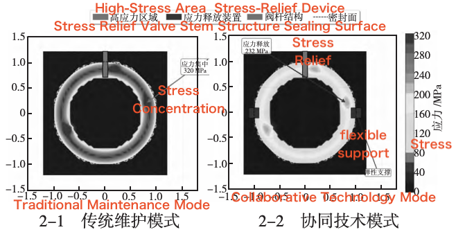
Figure 2. Stress Distribution on the Ball Valve Sealing Surface (Simulation)
- Complex geological conditions significantly affect the operational performance of ball valves and valve chambers in underground pipeline networks. The problems vary among different geological conditions and worsen as components age, making targeted maintenance technologies essential for improving network reliability.
- The established ball valve reliability maintenance system and valve chamber maintenance technologies enable coordinated maintenance of both ball valves and valve chambers through a synergistic approach, allowing key problems to be addressed effectively under different geological conditions.
- Experimental and simulation results show that the synergistic technology significantly reduces ball valve failure rates, improves the structural integrity of valve chambers, lowers maintenance costs, and enhances the operational reliability of the pipeline network.