Analysis and Remedial Measures for Operating Seal Leakage in Ball Valves of High-Head Pumped-Storage Units
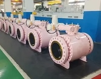
Abstract: In pumped-storage power stations, ball valves are critical to the safe and stable operation of the units, while their service seals play a vital role in preventing water leakage. Leakage from a service seal can have several adverse consequences:
- Waste water resources and reduce overall plant efficiency.
- Cause unit creep and induce self-excited vibration of the ball valve.
- Lead to secondary accidents, such as powerhouse flooding, posing a serious threat to equipment safety.
Taking a ball valve in a pumped-storage power station as a case study, this paper systematically investigates the causes of service seal leakage and proposes practical measures to rectify existing leakage problems and mitigate potential risks.
In recent years, hydraulic self-excited vibrations of ball valve have been reported at several pumped-storage power stations. In some cases, these vibrations have caused significant damage to valve bodies, posing a serious threat to plant safety and reliable operation. Investigations have shown that such vibrations are primarily associated with water leakage in the service seal system, including leakage into or out of the seal chambers and pressure fluctuations caused by hydraulic cross-talk between the chambers. Further research has revealed that leakage between the mating surfaces of the stationary and moving seal rings can also destabilize the seal. The resulting seal vibrations can induce pressure pulsations downstream of the valve. These pulsations may propagate upstream and interact with the seal, creating a feedback mechanism that amplifies the vibrations and can ultimately trigger self-excited oscillations in the water conveyance system. This paper investigates a ball valve used in a pumped-storage power plant, analyzes the causes of leakage at its service seal, and describes the remedial measures implemented. These measures are intended to eliminate the risk of self-excited vibration associated with seal leakage, thereby ensuring the safe and stable operation of the equipment.
A ball valve consists of a valve body, a valve disc (rotor), pivots, a maintenance seal, and a service seal. The maintenance seal and service seal are of similar design. Each consists of a stationary sealing ring (hereinafter referred to as the "stationary ring") fixed to the valve disc and a movable sealing ring (hereinafter referred to as the "moving ring") housed in the valve body and capable of axial movement. Under normal operating conditions, the maintenance seal remains retracted (disengaged). It is engaged only during unit maintenance or when the service seal requires maintenance, thereby providing a watertight barrier between the valve body and the downstream section. In contrast, the service seal automatically engages and disengages as the ball valve opens and closes.
As shown in the structural diagram of the service seal (Figure 1), when the ball valve disc is fully closed, the retraction control chamber (which controls seal disengagement) is connected to the drain line, while the engagement control chamber (which controls seal engagement) is supplied with high-pressure water. The hydraulic pressure pushes the moving ring toward the valve disc, bringing it into contact with the stationary ring and forming a watertight seal. When the ball valve is to be opened, the engagement control chamber is connected to the drain line, while the retraction control chamber is supplied with high-pressure water. The hydraulic force pushes the moving ring away from the valve disc, separating it from the stationary ring. The valve disc can then rotate to open the valve. The maintenance seal operates on the same principle as the service seal.
In February 2022, during the commissioning and trial operation of Unit 4 at a pumped-storage power plant, a distinct water leakage noise (indicating internal leakage) was detected at the service seal when the ball valve was fully closed and the service seal was engaged. The leakage was intermittent, with varying intensity. Furthermore, engaging and subsequently disengaging the maintenance seal often significantly reduced the leakage. By January 2023, the leakage noise had gradually diminished and had almost completely disappeared by February. However, in February 2024, the leakage noise reappeared and gradually intensified. During this period, the service seal underwent multiple inspections and tests, but no obvious abnormalities were found.
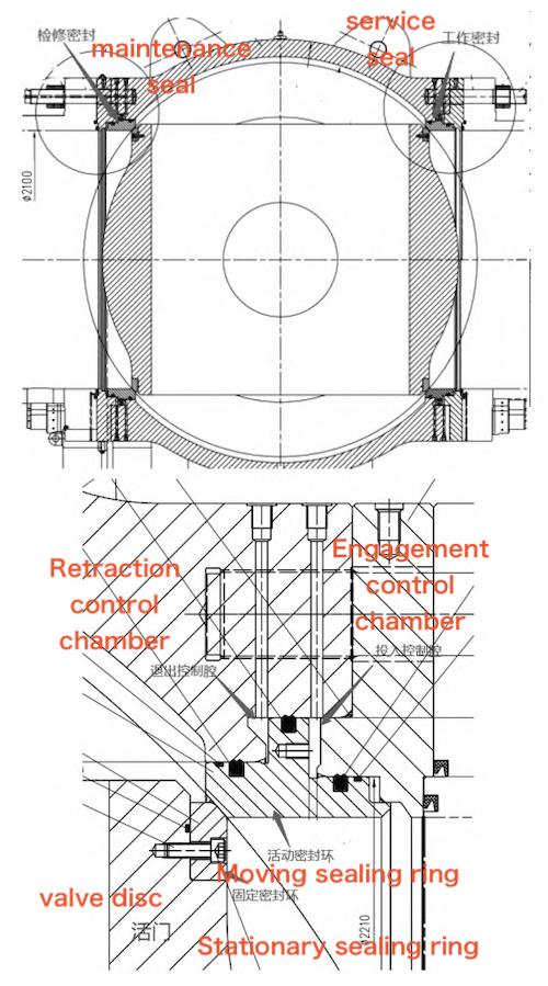
Figure 1. Schematic diagram of the ball valve and service seal structure
In May 2024, an inspection revealed that seven bolts securing the stationary ring at its base had fractured, and one bolt was missing. The stationary ring was originally secured with 72 M20 × 60 A2-70 hexagon socket head bolts, each tightened to a specified torque of 124 N·m and secured by two spot welds. Subsequently, all 72 bolts were replaced, and the specified tightening torque was increased from 124 N·m to 140 N·m. Following the replacement, no significant leakage noise was detected until the unit underwent a B-level maintenance overhaul in September 2024.
In October 2024, during the B-level maintenance of Unit 4, the sealing assembly, consisting of the moving and stationary rings, was disassembled for inspection. The sealing strip between the stationary ring and the lower section of the valve body, in the areas corresponding to the locations of the previously fractured or missing bolts, was found to be damaged and partially missing. The entire sealing pair, including both the moving and stationary rings, was subsequently replaced, completely eliminating the water leakage
In general, damage to the sealing surfaces of the moving and stationary rings is the most direct cause of leakage. Although maintenance personnel at the power plant and the equipment manufacturer had inspected the sealing rings several times and identified minor scratches on the sealing surfaces, the extent of this damage was considered insufficient to explain the observed leakage rate. Furthermore, leakage caused by damage to the sealing rings would typically increase progressively over time as high-velocity fluid jets erode and enlarge the damaged areas. This expected trend is inconsistent with the intermittent leakage and fluctuations in leakage intensity observed in this case. Therefore, damage to the sealing pair was ruled out as the primary cause of leakage.
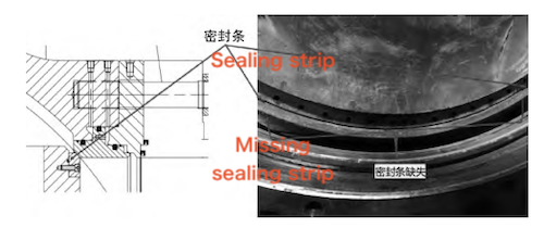
Figure 2. Damaged or Missing Sealing Strip
Based on an analysis of the service seal structure, foreign objects entering either the space between the moving and stationary rings or the space between the moving ring and the valve body within the retraction chamber may prevent the sealing rings from making full contact when the seal is engaged, resulting in leakage. Once the foreign objects are flushed away or crushed, the sealing rings can regain proper contact, allowing the leakage to cease. This mechanism could explain the intermittent leakage and fluctuations in leakage intensity described above.
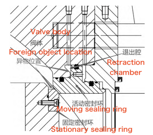
Figure 3. Schematic Illustration of Potential Foreign Object Locations That Could Cause Leakage
However, repeated cleaning and inspection of the retraction chamber revealed no foreign objects. Furthermore, the water supply system serving the engagement and retraction chambers is equipped with sediment-settling and precision filtration devices, making it unlikely that foreign objects could enter the sealing assembly through the water supply. In addition, the power plant generally maintains good water quality. Unit 3 shares the same flow passage as Unit 4 in a "one tunnel, two units" configuration, yet has never experienced similar leakage. Likewise, Units 1, 2, 5, and 6 have remained free of this problem. These findings suggest that foreign object intrusion is unlikely to be the cause of the leakage.
Damage to the seals in the engagement chamber or to those between the engagement and retraction chambers could impair the movement of the moving ring and lead to leakage. Alternatively, localized friction or jamming between the moving ring and the valve body or pressure ring could cause the pressure ring to tilt. This could prevent the moving and stationary rings from making proper contact, resulting in leakage. Manual operation tests of the engagement and retraction functions revealed no significant leakage from either chamber. When the seal was engaged, no gaps were observed between the moving and stationary rings. In addition, no significant pressure fluctuations or drainage were detected in the retraction chamber. These findings suggest that seal damage or pressure ring jamming or displacement was unlikely to be the cause of the leakage.
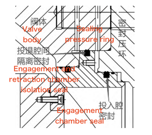
Figure 4. Schematic Diagram of the Engagement Chamber Seal Structure
If the closing angle of the ball valve disc varies from one operation to another, the contact conditions between the moving and stationary rings may also vary, potentially resulting in intermittent leakage or fluctuations in leakage intensity. To investigate this possibility, maintenance personnel repeatedly inspected the mounting bolts on the ball valve servomotor base and confirmed that they were securely tightened. Monitoring data, including the servomotor stroke, axial and radial displacement of the pivot, and deformation of the ball valve body, showed no significant differences between periods with and without leakage. Therefore, variations in the closing angle of the ball valve disc were considered unlikely to be the cause of the leakage.
3.5 Insufficient Preload or Loosening of the Stationary Ring Fastening Bolts and Damage to the Sealing Strip
The ball valve was assembled at the manufacturer's facility and shipped to the site as a complete unit. In addition, the stationary ring fastening bolts were secured with spot welds to prevent loosening. Since the initial occurrence of leakage, repeated inspections from inside the flow passage have confirmed that both the fastening bolts and the spot welds remain intact.
In May 2024, several bolts at the bottom of the stationary ring were found to be fractured or missing. The fractured bolts showed clear signs of bending and cavitation erosion caused by high-velocity fluid jets. The fastening bolts were subsequently replaced, the specified tightening torque was increased, and the proper operation of the service seal was verified. These measures significantly reduced the leakage. During the B-level overhaul of the unit (September–November 2024), the stationary ring was dismantled for inspection. The sealing strip between the stationary ring and the valve element was found to be damaged or missing in the areas corresponding to the locations of the missing bolts. This finding suggests that, in this case, sufficiently tight contact between the stationary ring and the valve element could maintain an effective seal even in the absence of the sealing strip, preventing audible leakage.
In November 2024, the sealing strip and both the moving and stationary rings were replaced during the overhaul, after which the leakage was completely eliminated. Based on these findings and the results of the maintenance work, damage to or loss of the sealing strip, together with the associated fastening bolt failure, was identified as the cause of the service seal leakage. A schematic illustration of the leakage mechanism is provided in Figure 5.
The analysis is as follows:
When the ball valve is closed and the service seal is engaged, an existing high-pressure leak between the valve disc and the stationary ring generates a significant outward thrust on the stationary ring. Although the moving ring is in contact with the stationary ring, it cannot press the stationary ring firmly against the valve disc. As a result, a high-pressure leakage jet persists between the stationary ring and the valve disc, causing noticeable leakage. When the maintenance seal is engaged under these conditions, the pressure of the high-pressure water at the valve disc drops rapidly, eliminating the outward thrust generated by the leakage jet. The hydraulic pressure in the engagement chamber then drives the moving ring against the stationary ring, pressing the stationary ring firmly against the valve disc and restoring an effective seal. Even after the maintenance seal is subsequently disengaged, no significant leakage occurs. This mechanism explains why engaging and then disengaging the maintenance seal reduces leakage from the service seal.
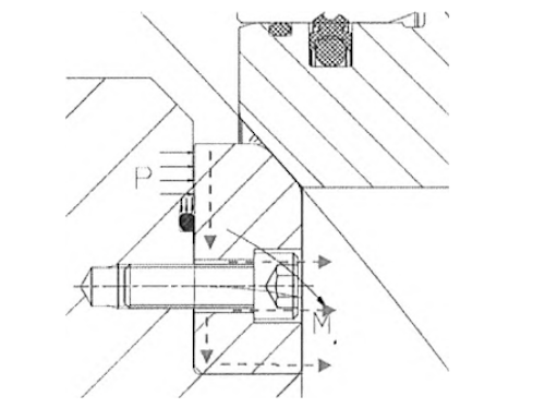
Figure 5. Schematic Illustration of the Service Seal Leakage Mechanism
Furthermore, the dismantling inspection revealed that sealing strip sections were missing at as many as 12 bolt locations. Given the manufacturer's strict installation procedures and the pressure and leakage tests conducted before shipment, it is unlikely that these sections were missing at the time of installation. They were therefore most likely dislodged during operation following fracture and subsequent erosion by the high-pressure leakage jet. If a fractured section of the sealing strip shifts under hydraulic impact and becomes lodged at the leakage site, it may partially fill the gap and temporarily restrict the leakage. However, as the fragment continues to move or is gradually eroded and washed away, significant leakage may recur. This mechanism explains the intermittent nature of the leakage and the fluctuations in its intensity.
Although loose or fractured fastening bolts and damaged or missing sealing strips were identified as the causes of the service seal leakage, the exact sequence of failure events could not be established. Specifically, it remains unclear whether the sealing strip was damaged first, allowing high-pressure leakage jets to develop and subsequently cause bolt failure, or whether the bolts loosened first, resulting in leakage that gradually eroded and damaged the sealing strip.
To prevent recurrence, the overhaul included both replacement of the sealing components and upgrades to the fastening bolts, including improvements in bolt strength and specified preload. The specific measures implemented are as follows:
(1) The entire sealing assembly was replaced, including the moving and stationary rings of the service seal and the sealing strip between the stationary ring and the valve element.
(2) The material grade of the bolts securing the stationary ring to the valve element was upgraded from A2-70 to C3-80 to increase their strength.
(3) The specified tightening torque for the bolts securing the stationary ring to the valve element was increased to 200 N·m, compared with the previously adjusted value of 140 N·m and the original value of 124 N·m.
(4) The weld size of the anti-loosening spot welds on the bolts was increased to reduce the risk of loosening due to weld failure.
Service seal leakage in a ball valve causes significant hydraulic losses and reduces the overall efficiency of a pumped-storage power plant. It may also trigger secondary problems, including unit creep, hydraulic self-excited vibration, and cavitation caused by high-velocity leakage jets in narrow gaps, such as those at the service seal or the end faces of guide vanes. These problems pose serious threats to the safe and stable operation of the plant. Therefore, the root causes of such leakage must be promptly identified and addressed.
This paper presents a case study of service seal leakage in the ball valve of Unit 4 at a pumped-storage power plant, detailing the investigation, troubleshooting, and corrective measures. The findings provide a reference for addressing similar problems. As pumped-storage power plants continue to develop, with increasing hydraulic heads, larger equipment dimensions, and growing adoption of single-penstock configurations serving multiple units, the reliability requirements for ball valve service seals are becoming increasingly stringent. Rigorous quality control should therefore be maintained throughout the design, manufacturing, and installation processes, and adequate safety margins should be ensured for sealing components and fasteners to prevent minor defects from developing into major failures.