Near-Net-Shape Forging of Cryogenic Valve Bonnets: Simulation and Experimental Study
In LNG, air separation, and petrochemical facilities, the lower bonnet of a forged steel valve designed for cryogenic service at −196 °C is a critical pressure-retaining component. Typically manufactured from F304L austenitic stainless steel, it must meet stringent requirements for:
- Mechanical strength
- Low-temperature toughness
- Corrosion resistance
Its geometry consists of an integral flange, cylindrical body, and connecting boss, making it an axisymmetric die forging. Conventional manufacturing methods for elongated, one-piece valve bonnets require substantial forging allowances and extensive flash removal, resulting in low material utilization and considerable post-forging machining.
In addition, F304L austenitic stainless steel has high deformation resistance and a relatively narrow hot-working temperature range. During die forging, these characteristics increase the risk of several defects, including:
- Incomplete die filling, particularly at corners
- Localized overheating
- Laps and folds
Because these defects cannot be repaired by welding, affected forgings must be scrapped. This significantly reduces production yield, particularly in mass production.
Near-net-shape die forging offers a solution by reducing machining allowances, reducing stainless steel material consumption, and shortening subsequent machining time. Finite element analysis (FEA) software, such as DEFORM-3D, enables metal flow to be simulated before actual die fabrication, allowing potential filling defects, stress and strain distributions, and temperature fields to be predicted. This helps reduce repeated trial runs, shorten process development cycles, and lower tooling tryout costs. Although researchers in China and abroad have extensively studied the hot-die forging of stainless steel and titanium alloy components, focusing on the effects of billet characteristics, die geometry, and process parameters on forming quality, few published studies have specifically addressed the near-net-shape forging of split-type lower bonnets for cryogenic valves.
In this context, FEA enables metal flow to be visualized and potential defect-prone areas to be identified before physical prototypes are made. By iteratively optimizing die geometry and process parameters, manufacturers can reduce the number of trial runs, shorten the development cycle, and lower trial-production costs. This study focuses on the lower bonnet of a split-body forged steel valve made of F304L stainless steel. Using DEFORM-3D, the entire hot-die-forging process was simulated to investigate the effects of workpiece characteristics, forging temperature, and pressing speed on the equivalent stress and strain distributions. The fillet radii of the multi-directional forging die were then optimized to achieve near-net-shape forming. Finally, the simulation results were validated through physical prototype production, providing a technical basis for the process design of similar cryogenic valve forgings.
According to Section 4.4.2.1 of the national standard GB/T 35079-2018, Principles for Process Preparation of Multi-directional Precision Forgings, dies must be preheated to 150–200 °C. During production, the die temperature is generally maintained at 200–400 °C. Appendix A, Table A.1, "Forging Temperature Ranges for Typical Materials," specifies an initial forging temperature of 1180 °C and a final forging temperature of 850 °C for F304 stainless steel. Considering that this study uses F304L stainless steel and referring to the applicable forging specifications for this material, the temperature for multi-directional near-net-shape forging is controlled within the range of 1150–1200 °C. Furthermore, Section 4.5.6 of GB/T 37057-2019, Quality Control Specifications for Multi-directional Precision Forgings, stipulates that, when a hydraulic press is used for multi-directional forging, the pressing speed must be at least 50 mm/s and the return speed must be at least 150 mm/s.
The near-net-shape forging process for the lower valve bonnet adopts a single-step multi-directional forging method. The process consists of blanking, heating, multi-directional forging, and post-forging treatment. The starting material is an F304L stainless steel bar with a diameter of 50 mm, cut to an initial length of 392 mm. The workpiece is heated to 1150 °C in a medium-frequency induction furnace. The holding time is strictly controlled according to the bar diameter to ensure uniform temperature distribution across the cross-section while preventing grain coarsening. Immediately after removal from the furnace, the workpiece is transferred to a multi-directional hydraulic forging press for single-step forming. The press speed is set to 150 mm/s, and the preheated die is maintained at 280 °C. After forging, the workpiece undergoes grinding, solution treatment, and pickling to ensure that it meets the mechanical property requirements for cryogenic service.
The multi-directional forging die is the key tooling that ensures the near-net-shape quality of the lower valve bonnet. Given the part's geometry—a lower flange, a central cylindrical body, and an upper boss—H13 hot-work tool steel was selected to withstand the 1150 °C forming temperature. A horizontal parting-line configuration is used, with the forging body contained within the upper and lower die cavities; forming is achieved by compression from lateral (left and right) punches, ensuring uniform metal flow. The die cavities are dimensioned precisely from the forging drawing, with allowances made for thermal contraction. For the octagonal profile at the lower end, an R3 mm fillet is applied to the flange corners to prevent dead zones—regions of poor material flow—during cavity filling. The die assembly uses four-corner locking together with high-precision guide pillars and bushings to maintain accurate alignment between the punches and the cavities. An ejection mechanism is also built in to support continuous mass production.
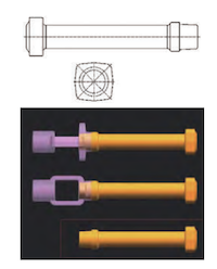
As shown in Figure 1, the forging has overall dimensions of Ø85 mm × 330 mm. It consists of a lower flange, a central cylindrical body, and an upper connecting boss, which serves as the mounting base for the upper support bracket. The forging weighs approximately 6 kg. Solid models of the forging, the multi-directional forging blank, and the forging dies were created in UG and exported in STL format for import into the DEFORM-3D simulation platform.
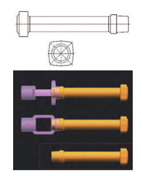
Figure 1. 3D model of the lower valve bonnet forging
The blank undergoes substantial plastic deformation during forging. In the DEFORM-3D preprocessor, the blank is defined as a plastic body, while the multi-directional forging dies are modeled as rigid bodies, with die elastic deformation neglected. The blank is meshed using tetrahedral elements, with a total of 50,000 elements, while the dies remain unmeshed. Figure 2 shows the meshed blank and the die simulation model.
The blank material is AISI 304 (used to approximate F304L), and the die material is AISI H13. The initial blank temperature is set to 1150 °C, the die temperature to 280 °C, and the pressing speed to 150 mm/s. The ambient temperature is 20 °C. The convective heat transfer coefficient between the blank and the environment is 0.02 N/(s·mm·°C), the emissivity is 0.7, and the heat transfer coefficient between the blank and the die is 0.03 N/(s·mm·°C). Shear friction is selected, with a friction factor of 0.3.
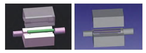
Figure 2. Die structure and simulation model
As shown in the 3D model of the lower valve bonnet forging, the lower flange has an octagonal profile and a relatively large thickness, making it prone to incomplete die filling during near-net-shape forging. The upper connecting boss has a circular profile and includes a machining allowance, making it relatively easy to form. Billets with lengths of 392 mm and 412 mm were cut from Ø50 mm bar stock and used in full-process multi-directional forging simulations. The two billet lengths were compared in terms of die filling, temperature distribution, equivalent stress, equivalent strain, and forming load.
Figure 3 presents the multi-directional forging simulation results for the two billet sizes. For the 392 mm billet, significant incomplete die filling occurs at the four corners of the lower flange, where the bolt holes are located for subsequent connection to the valve body. A small amount of flash forms around the upper boss, but its volume is negligible.
The billet volume is insufficient to completely fill the die cavities. Even at the end of the full forging stroke, unfilled regions remain at the flange corners, preventing the formation of a complete forging profile. According to Section 4.2.4 of ASTM A788/A788M-26a, Standard Specification for Steel Forgings, General Requirements, weld repair is not permitted for such steel forgings. The resulting forging must therefore be scrapped.
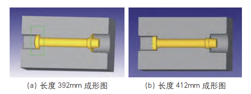
(a) Simulation result for the 392 mm billet (b) Simulation result for the 412 mm billet
Figure 3. Multi-directional forging simulation results for the two billet sizes
For the 412 mm billet, the simulation shows complete filling of the die cavities for the lower flange, cylindrical body, and upper sealing boss. The resulting flash is thin and uniform, indicating that the billet provides an appropriate volume of material to fill the die cavity without generating excessive flash. Based on these results, the 412 mm billet was selected for production. To further investigate the temperature field, equivalent stress and strain distributions, and forming load under different forging temperatures and pressing speeds, four simulation cases were established for comparison, as listed in Table 1.
Table 1. Simulation Cases
|
Case |
Billet Length (mm) |
Forging Temperature (°C) |
Pressing Speed (mm/s) |
|
1 |
412 |
1150 |
150 |
|
2 |
412 |
1200 |
150 |
|
3 |
412 |
1150 |
200 |
|
4 |
412 |
1200 |
200 |
Figure 4 shows the equivalent strain distributions in the forged part at billet temperatures of 1150 ℃ and 1200 ℃ and pressing speeds of 150 mm/s and 200 mm/s. A comparison of the four simulation cases shows that the equivalent strain is relatively low and uniformly distributed in the central cylindrical section and lower flange, while higher values occur at the upper connecting boss. The overall strain distribution pattern remains largely consistent under different temperatures and pressing speeds, although the equivalent strain increases as both parameters increase. The lower flange and the base of the upper sealing boss are identified as regions of concentrated deformation.
At a billet temperature of 1150 ℃, increasing the pressing speed from 150 mm/s to 200 mm/s increases the average equivalent strain by 23%. This is because a higher pressing speed reduces the time available for heat exchange between the forging and the die, thereby limiting the temperature drop caused by interfacial heat conduction. As a result, the forging remains at a higher temperature during deformation, reducing the flow stress and promoting plastic flow. At a pressing speed of 200 mm/s, increasing the billet temperature from 1150 ℃ to 1200 ℃ increases the average equivalent strain by 26.5%. This increase is attributable to enhanced thermal activation of metal atoms at higher temperatures, which improves the material's flowability and deformability. Overall, billet temperature has a more pronounced effect on equivalent strain than pressing speed.
Figure 5 shows the equivalent stress distribution in the workpiece at 1150 °C and 1200 °C and pressing speeds of 150 mm/s and 200 mm/s. The equivalent stress is relatively low in the central cylindrical section and the upper connecting boss, while the maximum equivalent stress occurs in the lower flange region. As the pressing speed increases, the equivalent stress generally decreases and its distribution becomes more uniform. At a workpiece temperature of 1200 °C, increasing the pressing speed from 150 mm/s to 200 mm/s reduces the average equivalent stress by 9.2%. This reduction is primarily attributable to differences in thermo-mechanical coupling. A higher pressing speed significantly shortens the deformation cycle, effectively suppressing the temperature drop caused by interfacial heat transfer. This allows the material to undergo dynamic recrystallization and softening over a higher temperature range, thereby reducing both deformation resistance and equivalent stress. Notably, at a pressing speed of 200 mm/s, raising the workpiece temperature from 1150 °C to 1200 °C lowers the average equivalent stress by a substantial 33%. This reduction is attributable to the high-temperature environment, which greatly enhances atomic thermal activation and diffusion, facilitating dynamic recrystallization and softening and, in turn, markedly improving the metal's plasticity and lowering the flow stress.
During hot-die forging, the temperature field within the forging is governed by two competing mechanisms: heat transfer from the hot workpiece to the cooler die across the interface, which causes a temperature drop, and the conversion of plastic deformation work into heat, which results in localized temperature increases. A comparison of the temperature distributions under the four simulation scenarios (Figure 6) shows that, at a constant initial billet temperature, changes in pressing speed have only a minor effect on the overall temperature distribution. The temperature variation across the forging at different pressing speeds remains within 30 ℃.
Specifically, at a billet temperature of 1150 ℃ and a pressing speed of 150 mm/s, the temperature throughout the forging body remains between 1140 and 1190 ℃, well within the optimal forging temperature range for F304L stainless steel. At a billet temperature of 1200 ℃ and a pressing speed of 200 mm/s, the average forging temperature is approximately 1200 ℃. Any localized high-temperature regions in the flash around the upper protrusion can be removed by grinding without affecting the microstructure or properties of the forging.
The forming load is an important basis for selecting multi-directional forging equipment and verifying die structural integrity. The load–displacement curve illustrates how the resistance to metal flow changes throughout the deformation process. Figure 7 shows the forming load–displacement curves for the four simulation cases. A comparison of the curves shows that, during the initial stage of forging, the metal undergoes only slight deformation, and the forming load remains relatively low. As the displacement increases, the metal progressively fills the die cavity, and the deformation resistance increases accordingly. As the die cavity approaches complete filling, the forming load rises sharply and reaches its peak.
Both the initial billet temperature and the pressing speed have a significant influence on the peak forming load. At a pressing speed of 150 mm/s, increasing the billet temperature from 1150 °C to 1200 °C reduces the peak forming load by 32%. This is primarily because higher temperatures promote dynamic recrystallization and associated softening, thereby reducing the flow stress and, consequently, the peak forming load. At a billet temperature of 1150 °C, increasing the pressing speed from 150 mm/s to 200 mm/s reduces the peak forming load by 12.5%. Furthermore, at a given initial billet temperature, a higher pressing speed shortens the deformation cycle and reduces the temperature drop in the billet. This helps maintain lower deformation resistance and slightly reduces the peak forming load.
Considering the characteristics of the actual multi-directional forging equipment, the simulation results, and the overall requirements for forming quality, equipment loading, and process stability, the optimal process parameters were determined to be a billet temperature of 1200 °C, a die preheating temperature of 280 °C, and a pressing speed of 150 mm/s. Under these conditions, the forming load remains stable, allowing the die cavity to be completely filled while minimizing excessive die wear and the risk of equipment overload.
To validate the DEFORM-3D simulation results, a small-batch trial production run was conducted using the optimal process parameters identified through simulation. A 392 mm billet was used first. As shown in Figure 8(a), the resulting underfill was consistent with the simulation predictions. A 412 mm billet was then used, as shown in Figure 8(b). The forged parts exhibited good overall quality, with the lower flange and upper boss fully formed and no signs of underfill, folding, or localized overheating. The measured dimensions were in good agreement with the DEFORM-3D predictions, confirming the reliability of the numerical model. The optimized process effectively addresses the quality issues encountered in the mass production of F304L stainless steel split-type lower valve bonnets and improves the production yield.
During trial production, sharp corners in the die cavity caused the workpiece to stick to the die. To improve production continuity and reduce material and labor waste caused by process interruptions, the die cavity was redesigned with rounded corners.
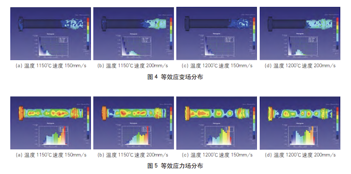
(a) 1150 °C, 150 mm/s (b) 1150 °C, 200 mm/s (c) 1200 °C, 150 mm/s (d) 1200 °C, 200 mm/s
Figure 4. Equivalent strain distribution
(a) 1150 °C, 150 mm/s (b) 1150 °C, 200 mm/s (c) 1200 °C, 150 mm/s (d) 1200 °C, 200 mm/s
Figure 5. Equivalent stress distribution
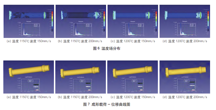
(a) 1150 °C, 150 mm/s (b) 1150 °C, 200 mm/s (c) 1200 °C, 150 mm/s (d) 1200 °C, 200 mm/s
Figure 6. Temperature distribution
(a) 1150 °C, 150 mm/s (b) 1150 °C, 200 mm/s (c) 1200 °C, 150 mm/s (d) 1200 °C, 200 mm/s
Figure 7. Forming load–displacement curves
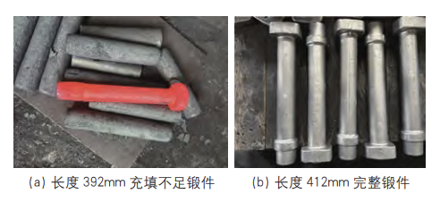
(a) 392 mm billet: forging with underfill (b) 412 mm billet: fully formed forging
Figure 8. Trial-forged parts
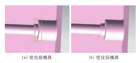
(a) Die before optimization (b) Die after optimization
Figure 9. Die cavity structure before and after optimization
Based on the defects identified in the simulations and feedback from on-site trial production, the die cavity was optimized to address die jamming and ejection difficulties caused by sharp corners at the upper boss of the forging. Specifically, the sharp corners in this region were rounded to a radius of 6 mm (R6), as shown in Figure 9. Subsequent trial forging confirmed that the parts could be ejected smoothly without die jamming. This modification not only improved production continuity by reducing material and labor waste associated with process interruptions but also further demonstrated the effectiveness of optimizing die cavity geometry for near-net-shape forming.
To address the common defects encountered during the multi-directional forging of F304L stainless steel split-type lower valve bonnets for service at −196 °C, including incomplete die filling, die jamming, and localized overheating, this study employed DEFORM-3D to conduct comprehensive numerical simulations of the hot-forging process. The effects of billet size, billet temperature, and pressing speed on the equivalent strain and stress distributions, temperature field, and forming load were systematically investigated. Based on the simulation results and feedback from on-site trial production, the causes of the defects were analyzed, and the die cavity geometry was iteratively optimized. Rounding the sharp corners at the upper boss to a radius of 6 mm (R6) effectively reduced metal flow resistance and resolved the die jamming and ejection problems. These improvements led to the development of an optimized near-net-shape forging process for the valve bonnet.
Practical application has demonstrated that finite element simulation can effectively predict potential die-filling defects and ejection problems in stainless steel pressure-bearing forgings before die manufacturing. This helps reduce the time and material consumed by repeated die trials and modifications, thereby shortening the process development cycle. The optimized process addresses key quality issues in the mass production of these forgings, improving the yield of F304L stainless steel forgings and reducing manufacturing costs. The findings provide a theoretical basis and practical engineering reference for developing near-net-shape forging processes for cryogenic stainless steel valve components used in LNG, air separation, and petrochemical plants.