How to Select Valves for Condensate Systems
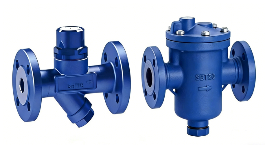
In industrial steam systems, condensate is not simply wastewater that needs to be removed. It is a valuable thermal fluid that directly affects heat-transfer performance, steam consumption, equipment reliability, and overall energy efficiency. When steam gives up its latent heat inside a heat exchanger, heating coil, jacketed vessel, or process line, the resulting condensate must be discharged efficiently while preventing the unnecessary escape of live steam. This is the fundamental function around which condensate system design is developed.
Valve selection therefore has a much broader significance than choosing a component with the correct pipe size. Engineers need to consider steam pressure, condensate load, differential pressure, back pressure, temperature, start-up conditions, air and non-condensable gases, water hammer, dirt, installation orientation, and required control characteristics. A valve that performs well under one set of operating conditions may become inefficient or unreliable under another.
A well-designed condensate system normally combines a properly selected steam trap with isolation valves, strainers, check valves, air vents, bypass arrangements, and appropriate control valves where required. These components work together to maintain stable drainage, protect equipment, simplify maintenance, and improve energy recovery.
The key engineering principle can be summarized as follows:
- Remove condensate quickly enough to maintain heat-transfer efficiency.
- Prevent live steam loss through the drainage system.
- Control water hammer and other transient conditions.
- Allow isolation and maintenance without unnecessary shutdowns.
- Protect steam traps and control valves from dirt and mechanical damage.
- Return clean condensate to the recovery system whenever practical.
Before selecting any valve, engineers should establish what type of condensate system is actually being designed. Industrial steam condensate systems and air-conditioning condensate drainage systems both involve water produced by condensation, but their physical mechanisms and engineering requirements are substantially different.
In a steam system, condensate is produced when steam transfers heat and changes from vapor to liquid. The condensate may still be at a relatively high temperature and pressure. A steam trap is therefore required to discharge liquid while restricting the passage of live steam. Pressure differential is often an important part of the drainage mechanism.
By contrast, an HVAC condensate drain usually collects relatively low-pressure water produced when humid air contacts a cooling coil below the air's dew point. The drainage system normally relies on gravity, proper pipe slope, trap seals, and sometimes condensate pumps. A conventional steam trap is generally not the appropriate device for this application.
This distinction is essential because the phrase "condensate valve" can refer to very different equipment depending on the application. Industrial designers should identify the source, temperature, pressure, flow characteristics, and intended drainage mechanism before selecting any valve.
A steam trap is an automatic valve designed to discharge condensate and non-condensable gases while minimizing the loss of live steam. Its operation is based on differences in physical or thermodynamic properties between steam, condensate, and air.
If condensate accumulates inside a heat exchanger or steam line, it can occupy heat-transfer surface that should otherwise be exposed to steam. In heat exchangers, this reduces the effective heat-transfer area and can increase process response time. In steam distribution piping, accumulated condensate can contribute to water hammer and mechanical stress.
At the same time, a steam trap that allows excessive steam leakage wastes energy and can overload the condensate return system. Therefore, good steam-trap selection is fundamentally a balance between drainage capacity and steam retention.
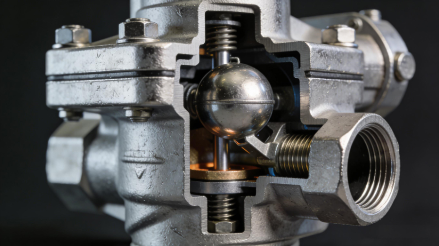
Free-floating ball or float-type steam traps are often selected for process heating applications because they can discharge condensate continuously as it forms. Their operating principle is based primarily on the density difference between condensate and steam.
When condensate enters the trap, the float rises and opens the discharge mechanism. As condensate is discharged and the liquid level falls, the float moves downward and reduces or closes the discharge opening. Because the valve responds directly to condensate level, the trap can provide continuous drainage under suitable operating conditions.
One major advantage is the ability to discharge condensate with relatively little subcooling. This characteristic can be valuable in process heating because condensate can leave the equipment at a temperature relatively close to the saturation temperature corresponding to its pressure.
Typical applications include:
- Steam-heated heat exchangers
- Process heaters
- Jacketed vessels
- Steam coils
- Steam mains under suitable drainage conditions
- General industrial heating equipment
However, the correct selection still depends on differential pressure and condensate load. A float trap should not be selected simply because the system is classified as a "steam application."
No single steam trap type is optimal for every operating condition. The major categories include mechanical traps, thermodynamic traps, and thermostatic traps. Understanding their operating characteristics helps engineers match the valve to the actual service.
Float traps are particularly suitable when continuous condensate discharge is desirable. Many designs also incorporate a thermostatic air-vent mechanism, allowing air and other non-condensable gases to be removed during start-up.
This combination can be valuable in process equipment because air trapped inside a heat exchanger can reduce effective heat transfer. The ability to remove air automatically can therefore influence both start-up performance and steady-state efficiency.
The main selection factors include differential pressure, maximum allowable pressure, condensate capacity, connection size, and resistance to contamination.
Inverted bucket traps use the buoyancy relationship between steam and condensate to operate an internal bucket mechanism. They are mechanically robust and can be suitable for applications where pressure and water hammer resistance are important considerations.
They are commonly considered for steam mains, process equipment, and other services where intermittent discharge is acceptable. Their operating characteristics differ from those of continuous-drainage float traps, so engineers should consider the required condensate removal rate and start-up behavior.
Inverted bucket traps can also provide useful air-handling characteristics depending on the specific design. However, they may require attention to installation details and should be protected from freezing where outdoor service is involved.
Thermodynamic disc traps are compact and comparatively simple devices. Their operation depends on the dynamic pressure effects created as condensate and steam pass through the trap.
These traps can tolerate relatively high pressures and are often used where compact construction and high-pressure service are important. They are particularly attractive for certain steam-main and high-pressure applications.
Nevertheless, disc traps have limitations. Their performance can be affected by operating conditions, back pressure, low differential pressure, and environmental temperature. They may also exhibit characteristic cycling or discharge sounds. Engineers should therefore verify the manufacturer's operating range rather than assuming that a high-pressure rating automatically makes a disc trap suitable for every high-pressure system.
Thermostatic traps operate primarily according to temperature differences between steam, condensate, and non-condensable gases. Common designs include bellows-type and bimetallic constructions.
These traps can be useful where subcooled condensate discharge is acceptable or desirable. They are therefore often considered for applications such as:
- Low-pressure heating systems
- Tracing systems
- Steam-jacketed lines
- Freeze protection
- Certain low-temperature process services
Their ability to discharge condensate below saturation temperature can reduce flash steam formation in some applications, but the resulting subcooling must be compatible with the process requirements. If the equipment requires rapid removal of condensate at near-saturation temperature, another trap technology may be more appropriate.
One of the most important engineering mistakes is selecting a steam trap based solely on nominal pipe diameter. The trap size and capacity should be determined by the actual condensate load and available differential pressure.
The condensate load may vary considerably between normal operation and start-up. A heat exchanger, for example, may produce a relatively high condensate rate during cold start-up and a lower rate once the equipment reaches operating temperature.
A basic selection process should consider:
| Parameter | Why It Matters |
|---|---|
| Steam inlet pressure | Determines operating pressure |
| Condensate pressure | Influences discharge conditions |
| Differential pressure | Determines available trap capacity |
| Condensate load | Determines required drainage capacity |
| Start-up load | Prevents undersizing during warm-up |
| Back pressure | Can reduce effective trap capacity |
| Temperature | Affects material and operating limits |
| Non-condensable gases | Influences air-venting requirements |
| Dirt and scale | Affects reliability and blockage risk |
| Installation elevation | Influences static head and drainage |
The available differential pressure should be evaluated under the least favorable operating condition rather than only under normal maximum pressure. A trap that appears adequately sized at maximum differential pressure may become undersized when downstream pressure increases.
Back pressure is one of the most frequently overlooked variables in steam-trap selection. The pressure downstream of the trap may come from a condensate return header, lifting the condensate to a higher elevation, a flash tank, another process stage, or a pressurized recovery system.
If the pressure downstream approaches the pressure upstream of the trap, the effective differential pressure becomes small. This can significantly reduce drainage capacity.
For this reason, engineers should calculate the actual operating differential pressure across the trap:
Differential pressure = Upstream pressure − Downstream pressure
The calculation should also consider static head and pressure fluctuations. If condensate must be lifted vertically after leaving the trap, the required pressure to overcome the elevation difference needs to be included in the hydraulic assessment.
This is particularly important in condensate return systems where multiple traps discharge into a common header.
A steam trap is an automatic device, but it should not normally be installed without considering how it will be isolated and maintained. Isolation valves are required so that the trap can be inspected, cleaned, repaired, or replaced without shutting down an entire plant section.
Gate valves are commonly used where the primary requirement is full isolation rather than throttling. Their relatively low flow resistance when fully open makes them suitable for many steam and condensate line isolation duties.
For example, a typical trap station may include:
Upstream isolation valve → Strainer → Steam trap → Check valve → Downstream isolation valve
The exact configuration depends on plant standards, service conditions, and manufacturer recommendations.
The isolation valve should be selected according to pressure class, temperature rating, connection standard, body material, and required leakage performance. The valve should also be accessible enough for operators and maintenance personnel to use safely.
Steam pipelines frequently contain rust, welding debris, scale, pipe sealant, and other contaminants, especially during commissioning or after maintenance work. Small internal clearances in steam traps can be vulnerable to these particles.
Installing a strainer upstream of the trap helps protect the operating mechanism and reduce the probability of blockage or abnormal operation.
A strainer should be selected according to:
- Maximum operating pressure
- Maximum operating temperature
- Required filtration level
- Pressure drop
- Drain or blowdown arrangement
- Material compatibility
- Maintenance accessibility
However, a strainer itself introduces pressure loss. Excessively fine filtration may create unnecessary pressure drop and increase maintenance frequency. The screen size should therefore be selected according to the sensitivity of the downstream equipment rather than simply choosing the finest available mesh.
A check valve can be important downstream of a steam trap where condensate may flow backward from a pressurized return header. Reverse flow can create undesirable operating conditions and potentially damage or interfere with the trap.
This is particularly relevant when several steam traps discharge into a common condensate return line. Pressure variations in the header can cause flow reversal if appropriate protection is not provided.
The check valve should be selected carefully because condensate systems can experience flashing, pressure fluctuations, and transient flow. A valve with unsuitable closing characteristics may itself contribute to water hammer.
Therefore, engineers should consider not only the nominal pressure rating but also the valve's dynamic response and suitability for the actual condensate service.
The selection of auxiliary valves should reflect their intended function rather than treating all valves as interchangeable.
Gate valves are generally designed for fully open or fully closed operation. When fully open, the flow passage can provide relatively low resistance compared with many throttling valves.
They are therefore commonly used for:
- Main steam isolation
- Condensate line isolation
- Equipment isolation
- Maintenance shutdown
- Sectional isolation
A gate valve should generally not be used as a routine flow-control device because prolonged throttling can cause undesirable flow conditions and seat damage.
Globe valves are better suited to applications where controlled pressure or flow adjustment is required. Their internal geometry allows the flow passage to be varied more progressively.
They may therefore be considered for:
- Flow adjustment
- Pressure reduction arrangements
- Bypass control
- Manual balancing
- Certain process control duties
The higher flow resistance of a globe valve is acceptable when controllability is more important than minimum pressure drop.
This functional separation—gate valves for isolation and globe valves for regulation—is a useful starting point for condensate system design, although actual valve selection should always follow the process requirements.
Non-condensable gases, especially air, can accumulate in steam systems and interfere with heat transfer. Even though air does not condense under normal steam-heating conditions, it can occupy space near heat-transfer surfaces and create a resistance layer.
Automatic air vents or suitable thermostatic air-vent mechanisms can therefore improve system performance, particularly during start-up.
High points in steam distribution systems may require particular attention because air tends to accumulate there. The exact arrangement depends on system geometry and operating conditions.
Effective air removal can provide several benefits:
- Faster equipment warm-up.
- More uniform heat transfer.
- Reduced risk of temperature stratification.
- Lower possibility of corrosion associated with certain stagnant conditions.
- More stable process temperature control.
Air removal should be treated as part of the overall steam system design rather than as an optional accessory.
Water hammer is one of the most serious mechanical hazards associated with poorly designed steam condensate systems. When condensate accumulates in a steam line and is subsequently accelerated by steam flow, large transient forces can occur.
Rapid valve closure can also generate pressure surges in liquid-filled condensate piping. These events can impose loads on valves, supports, flanges, pipe joints, and connected equipment.
Valve selection alone cannot eliminate water hammer. The entire piping arrangement must be evaluated.
Important design considerations include:
- Proper pipe slope
- Adequate drainage points
- Correct trap positioning
- Avoiding unnecessary low points
- Appropriate valve closing characteristics
- Proper support and anchoring
- Controlled start-up procedures
- Correct condensate return pressure
- Prevention of excessive condensate accumulation
Where severe transients are expected, engineers should consider dynamic analysis rather than relying only on static pressure calculations.
Hot condensate contains significant sensible heat and can also contain recoverable energy through pressure reduction and flash steam generation. Returning condensate to the boiler feedwater system can therefore reduce water treatment requirements, chemical consumption, and fuel demand.
The design of the condensate recovery system should consider:
- Condensate temperature
- Return pressure
- Flash steam generation
- Pumping requirements
- Contamination risk
- Storage tank capacity
- Recovery distance
- Elevation differences
- Heat losses in return piping
A steam trap should therefore be evaluated not only as an individual valve but also as one component in a larger energy-recovery system.
If condensate is discharged into a low-pressure return header, part of the high-pressure condensate may flash into steam. This flash steam can sometimes be recovered for lower-pressure heating applications. The design must account for the resulting two-phase flow and pressure conditions.
Material selection is another important part of valve engineering. Carbon steel, stainless steel, cast iron, ductile iron, bronze, and specialized alloys may all be used in different sections of condensate and steam systems.
The appropriate material depends on pressure, temperature, corrosion environment, fluid chemistry, and applicable design standards.
For example, high-temperature steam service often requires materials with suitable high-temperature strength, while corrosive condensate may justify stainless steel or other corrosion-resistant materials.
Material selection should therefore consider the entire pressure-temperature envelope rather than simply choosing a material based on nominal pipe size.
Sealing materials are equally important. Elastomers used in auxiliary valves must be compatible with the actual temperature and chemical environment. For high-temperature steam service, engineers must verify the temperature limits and long-term stability of all soft components.
Industrial condensate valves are available with threaded, socket-weld, butt-weld, flanged, and other connection configurations. The connection type should match the piping design and maintenance philosophy.
Flanged connections can facilitate equipment replacement and maintenance, while welded connections may reduce potential external leakage points in permanent high-temperature piping. Threaded connections may be suitable for smaller lines under appropriate pressure and temperature conditions.
Pressure class selection should also be based on the actual pressure-temperature rating of the valve and connection system. Nominal pressure designations should never be treated as interchangeable across different standards without verification.
Engineers should confirm:
- Valve pressure-temperature rating
- Flange standard
- Facing type
- Pipe schedule or wall thickness
- Connection dimensions
- Gasket compatibility
- Bolt material and rating
- Applicable piping code
Although industrial steam condensate is the primary focus of this article, HVAC condensate drainage deserves separate consideration because its valve requirements are fundamentally different.
For fan coil units, air-handling units, and other cooling equipment, condensate forms on the cooling coil when the coil surface temperature falls below the air dew point. The resulting water normally flows through a drain pan and condensate piping.
A motorized two-way valve may be installed on the chilled-water side of a fan coil unit to regulate chilled-water flow. However, this valve controls the cooling-water circuit, not the condensate drain itself.
The condensate drainage system typically depends on:
- Correct pipe slope
- Adequate drain diameter
- Properly designed water seal
- Accessible cleanout points
- Correct drain-pan connection
- Condensate pump where gravity drainage is impossible
A properly designed water trap can prevent air from being drawn through the condensate drain when negative pressure exists at the fan coil or air-handling unit.
Condensate drainage lines should normally be arranged to maintain continuous drainage toward the discharge point. Incorrect slope can create stagnant water, increasing the risk of microbial growth, odors, blockage, and overflow.
The water seal must also be designed according to the static pressure conditions at the equipment. If the pressure differential exceeds the available water-seal depth, the trap can be pulled dry or blown through, allowing air to bypass the intended drainage path.
Therefore, HVAC condensate design should evaluate both hydraulic drainage and air-pressure conditions.
This is particularly important for negative-pressure air-handling units. The required trap configuration and depth should be calculated rather than selected solely from a generic standard detail.
Several recurring mistakes can reduce condensate system performance even when the individual valves appear to meet nominal specifications.
A DN25 trap is not automatically appropriate for a DN25 condensate line. Trap capacity depends on differential pressure and operating conditions. The trap should be sized according to the actual condensate load.
Start-up condensate loads can be substantially higher than steady-state loads. A trap selected only for normal operating conditions may struggle during equipment warm-up.
High downstream pressure can significantly reduce trap capacity. This problem is especially common in shared condensate return systems.
A globe or control valve may be capable of shutting flow, but selecting it solely for isolation can create unnecessary pressure loss and cost. Conversely, using a gate valve for continuous throttling can damage the valve.
Even a well-designed steam trap can malfunction if welding debris and scale reach its internal mechanism. Upstream filtration is therefore an important reliability measure.
A system may operate correctly under steady-state conditions but experience severe mechanical stress during start-up or shutdown. Transient conditions should be included in the design review.
A systematic selection procedure can significantly reduce engineering errors.
Identify whether the system handles steam condensate, chilled-water condensate, process condensate, contaminated condensate, or another liquid. Do not select the valve until the fluid and process function are clearly defined.
Record:
- Normal pressure
- Maximum pressure
- Minimum pressure
- Normal temperature
- Maximum temperature
- Condensate flow
- Start-up flow
- Back pressure
- Ambient temperature
Decide whether the valve must isolate, regulate, automatically drain, prevent reverse flow, remove air, or protect downstream equipment.
Match the function to the valve technology. For steam drainage, evaluate float, inverted bucket, thermodynamic, and thermostatic traps. For isolation, consider gate or suitable quarter-turn valves. For regulation, consider globe or dedicated control valves. For reverse-flow protection, evaluate appropriate check-valve designs.
Confirm body material, trim, sealing materials, pressure-temperature rating, and connection standard.
Ensure that the valve can be accessed, isolated, cleaned, tested, and replaced. Maintenance accessibility is part of valve selection, not an afterthought.
Finally, examine water hammer, condensate recovery, flash steam, pressure drop, air removal, pipe slope, and control interaction. A valve should be evaluated as part of the complete system rather than as an isolated component.
For a typical industrial steam-heating application, a practical arrangement may include the following components:
| Position | Component | Primary Function |
|---|---|---|
| Steam/condensate inlet | Isolation valve | Equipment isolation |
| Before steam trap | Strainer | Remove debris |
| Main drainage point | Steam trap | Automatic condensate discharge |
| After trap | Check valve | Prevent reverse flow |
| Downstream | Isolation valve | Maintenance isolation |
| High point | Air vent | Remove non-condensable gases |
| Recovery system | Control/isolation valve | Manage condensate return |
| Process equipment | Appropriate control valve | Regulate steam or heating medium |
The exact arrangement should be adapted to the equipment, piping layout, pressure conditions, and plant standards.
Even correctly selected valves require regular inspection. Steam traps can fail in either an open or closed condition. A trap stuck open may discharge live steam continuously, while a trap stuck closed can cause condensate accumulation.
Maintenance programs should therefore include:
- Visual inspection for leakage and corrosion.
- Temperature or ultrasonic testing where appropriate.
- Verification of trap operation.
- Strainer inspection and cleaning.
- Check-valve inspection where reverse flow is suspected.
- Verification of isolation-valve condition.
- Inspection for abnormal vibration and water hammer.
- Review of condensate return temperature and pressure.
- Periodic comparison of actual performance with design conditions.
A trap-management program can help identify failed traps before they cause significant energy loss or process problems.
Condensate valve selection is fundamentally a system-engineering task. The objective is not simply to install a valve with the correct nominal diameter or pressure rating, but to create a drainage and recovery system that removes condensate reliably, minimizes live-steam loss, controls water hammer, protects equipment, and supports efficient energy recovery.
For industrial steam applications, the steam trap is the central component. Float-type traps can provide continuous drainage and are widely suited to process heating, while inverted bucket, thermodynamic, and thermostatic traps offer different advantages for specific pressure, temperature, start-up, and drainage requirements. The final choice must be based on condensate load, differential pressure, back pressure, air removal requirements, and installation conditions.
Auxiliary valves are equally important. Gate valves are generally suited to isolation, while globe valves and dedicated control valves are better suited to regulation. Strainers protect sensitive valve mechanisms, check valves prevent reverse flow, and air vents help eliminate non-condensable gases. Together, these components form an integrated condensate-management system.
For HVAC condensate drainage, the design philosophy is different. Proper slope, water seals, drain capacity, and condensate pumps are generally more important than industrial steam traps. Motorized two-way valves may be used for chilled-water control at fan coil units, but they should not be confused with the condensate drainage function itself.
Ultimately, the most reliable approach is to begin with the process conditions and required function, then select the valve technology, materials, pressure class, connection type, and accessories accordingly. When valve selection is integrated with piping design, condensate recovery, maintenance planning, and transient-flow control, the result is a safer, more efficient, and more durable condensate system.
