Válvulas de bola de tres vías

La válvula de bola de tres vías tipo O de la serie tiene características de gran capacidad de circulación, estructura compacta, buen rendimiento de sellado, larga vida útil, etc., económica y práctica, y fácil de mantener. Es ampliamente utilizado en petróleo, productos químicos, gas natural, energía eléctrica, metalurgia, alimentos, productos farmacéuticos y otras ocasiones con requisitos estrictos. También se puede aplicar a agua, vapor, petróleo, gas licuado, gas natural, gas de carbón y otros medios.
Además, se pueden seleccionar tratamientos de endurecimiento especiales de acuerdo con las necesidades del cliente, adecuados para -196 - 400 ℃, lo que brinda aplicaciones más seguras y extensas.
Válvula de bola con brida de tres vías

Válvula de bola de rosca de tres vías

Características
1. El cuerpo de la válvula adopta una fundición o forja de precisión, con una estructura compacta y una apariencia hermosa. El carrete y el vástago de la válvula de bola de tres vías tipo O realizan un movimiento giratorio. Cuando se gira el carrete, el carrete
y los asientos de las válvulas siempre están en estrecho contacto entre sí, lo que tiene una fuerte capacidad de corte;
2. El asiento de la válvula puede diseñarse para ser precargado por un resorte cilíndrico o un resorte de mariposa, con compensación automática, autosellado y alivio de presión automático en la cavidad de la válvula, adecuado para altas temperaturas y alta
ocasiones de presión;
3. El diseño giratorio de la bola de la válvula puede garantizar el buen funcionamiento de la bola de la válvula y reducir el par de operación;
4. Hay sellos blandos y duros opcionales, y la superficie de sellado se puede endurecer, adecuada para una variedad de condiciones de trabajo;
5. El diseño de alivio de presión automático de la cavidad central de la válvula. Cuando la temperatura media de la cavidad del cuerpo de la válvula aumenta y provoca un aumento anormal de la presión, no es necesario que pase por la válvula de seguridad. Aún así, puede aliviar automáticamente la presión solo por la función del asiento de la válvula, lo que mejora la seguridad de la válvula cuando transporta un medio líquido.
6. Rescate de inyección de grasa de emergencia, en algunas ocasiones especiales, debido a objetos extraños en el medio o fuego causado por la falla accidental del sello del asiento de la válvula, la válvula de inyección de grasa proporciona una conexión rápida con la pistola de inyección de grasa, que es conveniente y rápido para inyectar la grasa de sellado en la parte de sellado del asiento de la válvula Para mitigar la fuga;
7. Válvula de bola Diseño antiestático, Diseño antivuelco del vástago de la válvula;
8. El diseño de vástago alargado es adecuado para aplicaciones de baja temperatura;
9. Válvula de bola de tres vías Cualquier puerto se puede usar como entrada sin fugas. Se puede convertir en canales en forma de L o en forma de T según las condiciones de trabajo, lo que hace que la instalación sea más conveniente;
10. La inspección y el mantenimiento se pueden realizar sin quitar todo el cuerpo de la válvula después de liberar la presión del sistema;
11. Las válvulas de bola de tres vías se dividen en tipo L y tipo T. El tipo L es adecuado para la conmutación de flujo medio, que puede conectar dos canales perpendiculares entre sí. El tipo T es adecuado para división media, confluencia o cambio de dirección de flujo;
12. La válvula de bola de tres vías sellada de dos asientos tiene una estructura compacta, una apariencia hermosa y un buen rendimiento de sellado. Puede cambiar la dirección del flujo del medio de la tubería y también puede conectar o cerrar los dos
canales perpendiculares;
13. La válvula de bola de tres vías sellada de cuatro asientos tiene una forma hermosa y una estructura razonable, que no solo puede cambiar la dirección del flujo medio, sino también hacer que los tres canales se comuniquen entre sí.
otro, y controle de manera flexible la combinación o el flujo dividido del medio en la tubería;
14. Cualquier puerto de la válvula de bola de cuatro vías se puede usar como entrada sin fugas y se puede convertir en varios tipos de canales de acuerdo con las condiciones de trabajo, lo que hace que la instalación sea más conveniente;
15. La válvula de bola de cuatro vías sellada de cuatro plazas tiene una forma hermosa y una estructura razonable, que no solo puede cambiar la dirección del flujo medio, sino también hacer que los cuatro canales se comuniquen entre sí.
y controle de manera flexible la fusión o el flujo dividido del medio en la tubería.
Materiales de las piezas principales
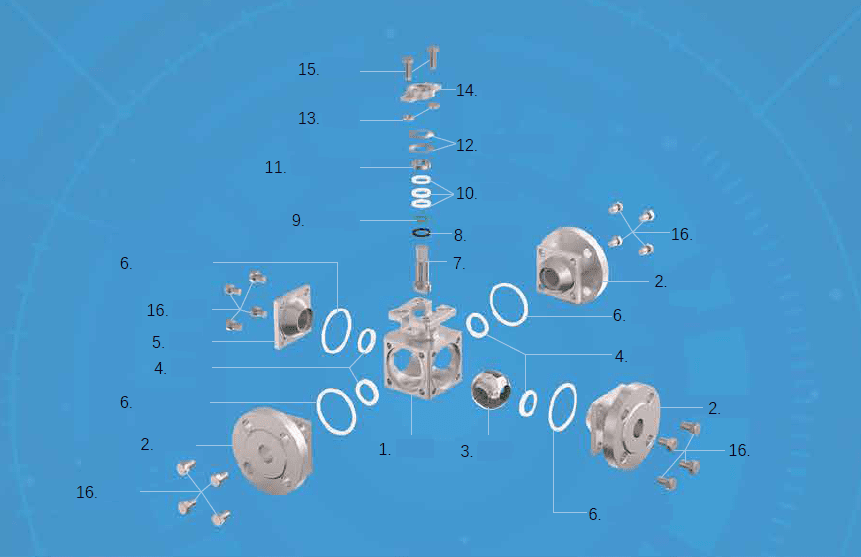
| NO. | Part Name | Material |
| 1 | Body | ASTM A216 WCB, ASTM A351 CF8, ASTM A351 CF8M, CF3M |
| 2 | Bonnet | ASTM A216 WCB, ASTM A351 CF8, ASTM A351 CF8M, ASTM A351 CF3M |
| 3 | Ball body | SS 304, SS 316, SS 316L, SS 316L + STL |
| 4 | Seat | PTFE, PPL, Metal seal, etc. |
| 5 | Cover board | ASTM A216 WCB, ASTM A351 CF8, ASTM A351 CF8M, ASTM A351 CF3M |
| 6 | Middle head gasket | PTFE, PPL, Metal gasket |
| 7 | Stem | SS 304, SS 316, SS 316L, 17-4PH, S20910 |
| 8 | Inverted seal | PTFE, PPL, Stainless steel wound graphite |
| 9 | O-ring | VITON |
| 10 | Filler | PTFE, PPL, Flexible graphite |
| 11 | Filling clamping ring | SS 304 |
| 12 | Butterfly spring | SS 304 |
| 13 | NUT | 2H, SS 304 |
| 14 | Gland of valve | ASTM A351 CF8 |
| 15 | Screw | ASTM B7, SS 304 |
| 16 | Screw | ASTM B7, SS 304 |
Schematic diagram of three-way flow


Product Specifications
| Nominal pressure | PN1.6-42MPa, ANSI 150 LB-2500 LB |
| Nominal diameter(mm) | DN15-DN400 |
| Connection Type | Flange, Thread, Butt welding, Socket welding |
| Body material | LCB, WCB, CF8, CF8M, CF3, CF3M |
| Valve seat form | Soft seat, metal seat (hardened sealing surface) |
| Proper temperature | Soft seat: -20 - +200℃, Metal seat: -196 - +400℃ |
| Leakage level | ANSI VI |
| Design standards | GB/T 12237, ASME B16.34 |
| Structure length | GB/T 12221, ASME B16.10 |
| Testing standards | GB/T 13927, API 598 |
| Operation method | Manual, pneumatic, electric, etc. |
| Optional | Anti-static design, fire protection design, oil-free treatment, Copper Prohibition, Spherical special treatment, Customers request painting |
Product structure design features
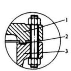
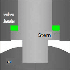
1. Valve stem anti-blowing structure design (see picture 1)
In valve stem anti-blowing structure design, the lower end is larger and the upper end is smaller. The positioning of the upper-end cover and screws, even in the valve cavity is abnormal. In this case of, it can also ensure that the valve stem will not be blown out by the medium.
picture 1
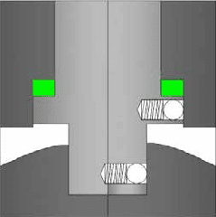
2. Anti-static design (See picture 2)
The fixed ball valve adopts an anti-static design to make the ball, stem and valve. The body forms an electrostatic channel so that the ball and the seat are switched. During the process, static electricity generated by friction is led to the ground through the valve body, Preventing the risk of fire or explosion caused by static sparks.
picture 2
KV rated
| SIZE | DN15 | DN20 | DN25 | DN32 | DN40 | DN50 | DN65 | DN80 | DN100 | DN125 | DN150 | DN200 | DN250 | DN300 |
| Kv | 26 | 65 | 91 | 150 | 265 | 480 | 750 | 1260 | 2300 | 3800 | 5400 | 9900 | 15000 | 25000 |
Soft seal torque table (N.m)
| SIZE | DN15 | DN20 | DN25 | DN32 | DN40 | DN50 | DN65 | DN80 | DN100 | DN125 | DN150 | DN200 | DN250 | DN300 |
| PN16 | 8 | 12 | 18 | 29 | 35 | 65 | 89 | 120 | 220 | 500 | 800 | 1400 | 1950 | 2620 |
| PN25 | 10 | 14 | 22 | 40 | 50 | 80 | 120 | 160 | 280 | 650 | 1000 | 1700 | 2400 | 3740 |
| PN40 | 14 | 20 | 48 | 60 | 70 | 100 | 200 | 300 | 500 | 900 | 1400 | 1992 | 3380 | 5600 |
| PN63 | 30 | 60 | 100 | 130 | 160 | 200 | 400 | 600 | 800 | 1200 | 1780 | 3000 | 5120 | 8580 |
| PN100 | 38 | 70 | 136 | 200 | 260 | 380 | 760 | 920 | 1540 | 1310 | 3780 | 6560 | 10500 | 14400 |
| PN160 | 48 | 88 | 170 | 250 | 306 | 476 | 900 | 1150 | 1926 | 2096 | 4639 | 8232 | 11820 | 20274 |
| CL150 | 9 | 14 | 26 | 36 | 48 | 75 | 100 | 150 | 270 | 600 | 940 | 1560 | 2210 | 3310 |
| CL300 | 17 | 25 | 55 | 90 | 110 | 140 | 280 | 350 | 620 | 1050 | 1600 | 2400 | 3472 | 4776 |
| CL600 | 38 | 70 | 136 | 200 | 260 | 380 | 720 | 920 | 1540 | 1310 | 3780 | 6560 | 10500 | 14400 |
| CL900 | 48 | 88 | 170 | 250 | 306 | 476 | 900 | 1150 | 1926 | 2096 | 4639 | 8232 | 11820 | 20274 |
| CL1500 | 64 | 110 | 230 | 285 | 342 | 592 | 1126 | 1436 | 2408 | 3810 | 7630 | 14430 | 21980 | 32206 |
| CL2500 | 98 | 165 | 345 | 430 | 520 | 1178 | 1472 | 3154 | 3930 | 4912 | 11002 | 23572 | 26444 | 40150 |
four-way ball valve.
Hard seal torque table (N.m)
| SIZE | DN15 | DN20 | DN25 | DN32 | DN40 | DN50 | DN65 | DN80 | DN100 | DN125 | DN150 | DN200 | DN250 | DN300 |
| PN16-L | 18 | 22 | 31 | 42 | 62 | 88 | 126 | 192 | 308 | 650 | 1000 | 1600 | 2300 | 3000 |
| PN16-T | 34 | 42 | 59 | 80 | 118 | 167 | 239 | 365 | 585 | 1087 | 1630 | 2508 | 3302 | 5329 |
| PN25-L | 20 | 25 | 40 | 75 | 83 | 115 | 176 | 264 | 396 | 803 | 1320 | 2035 | 2453 | 4015 |
| PN25-T | 38 | 47 | 76 | 142 | 158 | 218 | 334 | 502 | 752 | 1526 | 2508 | 3866 | 4660 | 7628 |
| PN40-L | 22 | 33 | 59 | 112 | 132 | 165 | 264 | 451 | 676 | 1265 | 2156 | 2750 | 3619 | 6006 |
| PN40-T | 42 | 63 | 112 | 213 | 251 | 313 | 502 | 857 | 1284 | 2403 | 4096 | 5225 | 6876 | 11411 |
| PN63-L | 27 | 46 | 77 | 165 | 211 | 286 | 429 | 726 | 1023 | 2090 | 3245 | 4620 | 6116 | 9427 |
| PN63-T | 51 | 87 | 146 | 313 | 400 | 543 | 815 | 1379 | 1944 | 3971 | 6165 | 8778 | 11620 | 17900 |
| PN100-L | 33 | 60 | 115 | 213 | 330 | 286 | 517 | 946 | 1452 | 2178 | 3157 | 5874 | 10186 | 14982 |
| PN100-T | 63 | 114 | 218 | 405 | 627 | 543 | 982 | 1797 | 2759 | 4138 | 5998 | 11160 | 19353 | 28466 |
| PN160-L | 42 | 93 | 170 | 297 | 429 | 429 | 781 | 1419 | 2145 | 3432 | 4928 | 8635 | 17050 | 24700 |
| PN160-T | 80 | 178 | 323 | 564 | 815 | 815 | 1484 | 2696 | 4075 | 6521 | 9363 | 16406 | 32395 | 46900 |
| CL150-L | 19 | 23 | 37 | 62 | 68 | 103 | 143 | 225 | 341 | 671 | 1078 | 1595 | 2035 | 3685 |
| CL150-T | 36 | 44 | 70 | 118 | 129 | 196 | 272 | 427 | 648 | 1275 | 2048 | 3030 | 3866 | 6999 |
| CL300-L | 24 | 35 | 71 | 129 | 154 | 235 | 324 | 605 | 825 | 1628 | 2651 | 3971 | 4917 | 7645 |
| CL300-T | 46 | 66 | 125 | 245 | 293 | 446 | 616 | 1150 | 1567 | 3093 | 5037 | 7545 | 9342 | 14525 |
| CL600-L | 33 | 60 | 115 | 213 | 330 | 286 | 517 | 946 | 1452 | 2178 | 3157 | 5874 | 10186 | 14982 |
| CL600-T | 63 | 114 | 218 | 405 | 627 | 543 | 982 | 1797 | 2759 | 4138 | 5998 | 11160 | 19353 | 28466 |
| CL900-L | 42 | 93 | 170 | 297 | 429 | 429 | 781 | 1419 | 2145 | 3432 | 4928 | 8635 | 17050 | 24700 |
| CL900-T | 80 | 178 | 323 | 564 | 815 | 815 | 1484 | 2696 | 4075 | 6521 | 9363 | 16406 | 32395 | 46900 |
Note: The black part is the torque table of the floating three-way four-way ball valve, and the red part is the torque table of the fixed three-way four-way ball valve.
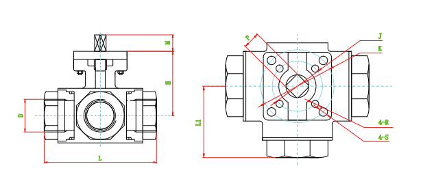
Three-Way Flange Ball Valve
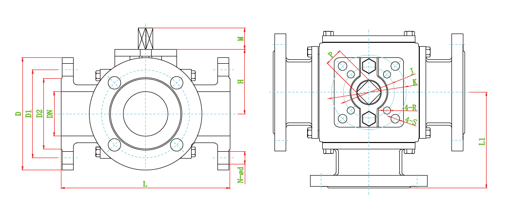
GB PN16 Main dimensions table (Unit: mm)
|
SIZE |
L |
L1 |
D2 |
D1 |
D |
N-ø d |
M |
H |
J |
K |
P |
R |
S |
|
DN15 |
150 |
75 |
45 |
65 |
95 |
4-ø 14 |
13 |
58 |
42 |
50 |
11 |
6 |
7 |
|
DN20 |
160 |
80 |
58 |
75 |
105 |
4-ø 14 |
16 |
61 |
50 |
70 |
14 |
7 |
9 |
|
DN25 |
180 |
90 |
68 |
85 |
115 |
4-ø 14 |
16 |
72 |
50 |
70 |
14 |
7 |
9 |
|
DN32 |
200 |
100 |
78 |
100 |
140 |
4-ø 18 |
16 |
81 |
50 |
70 |
14 |
7 |
9 |
|
DN40 |
220 |
110 |
88 |
110 |
150 |
4-ø 18 |
19 |
103 |
70 |
102 |
17 |
9 |
11 |
|
DN50 |
240 |
120 |
102 |
125 |
165 |
4-ø 18 |
19 |
113 |
70 |
102 |
17 |
9 |
11 |
|
DN65 |
260 |
130 |
122 |
145 |
185 |
8-ø 18 |
19 |
120 |
70 |
102 |
17 |
9 |
11 |
|
DN80 |
280 |
140 |
138 |
160 |
200 |
8-ø 18 |
24 |
162 |
125 |
140 |
22 |
14 |
18 |
|
DN100 |
320 |
160 |
158 |
180 |
220 |
8-ø 18 |
24 |
184 |
125 |
140 |
22 |
14 |
18 |
|
DN125 |
380 |
190 |
188 |
210 |
250 |
8-ø 18 |
29 |
215 |
140 |
165 |
27 |
18 |
22 |
|
DN150 |
440 |
220 |
212 |
240 |
285 |
8-ø 22 |
29 |
250 |
140 |
165 |
27 |
18 |
22 |
|
DN200 |
550 |
275 |
268 |
295 |
340 |
12-ø 22 |
38 |
334 |
|
165 |
36 |
|
22 |
|
DN250 |
670 |
335 |
320 |
355 |
405 |
12-ø 26 |
|
380 |
|
165 |
|
|
|
|
DN300 |
850 |
425 |
378 |
410 |
460 |
12-ø 26 |
|
405 |
|
165 |
|
|
|
GB PN25-PN40 Main dimensions table (Unit: mm)
|
SIZE |
L |
L1 |
D2 |
D1 |
D |
N-ø d |
M |
H |
J |
K |
P |
R |
S |
|
|
DN15 |
150 |
75 |
45 |
65 |
95 |
4-ø 14 |
13 |
58 |
42 |
50 |
11 |
6 |
7 |
|
|
DN20 |
160 |
80 |
58 |
75 |
105 |
4-ø 14 |
16 |
61 |
50 |
70 |
14 |
7 |
9 |
|
|
DN25 |
180 |
90 |
68 |
85 |
115 |
4-ø 14 |
16 |
72 |
50 |
70 |
14 |
7 |
9 |
|
|
DN32 |
200 |
100 |
78 |
100 |
140 |
4-ø 18 |
16 |
81 |
50 |
70 |
14 |
7 |
9 |
|
|
DN40 |
220 |
110 |
88 |
110 |
150 |
4-ø 18 |
19 |
103 |
70 |
102 |
17 |
9 |
11 |
|
|
DN50 |
240 |
120 |
102 |
125 |
165 |
4-ø 18 |
19 |
113 |
70 |
102 |
17 |
9 |
11 |
|
|
DN65 |
290 |
145 |
122 |
145 |
185 |
8-ø 18 |
19 |
120 |
70 |
102 |
17 |
9 |
11 |
|
|
DN80 |
310 |
155 |
138 |
160 |
200 |
8-ø 18 |
24 |
177 |
125 |
140 |
22 |
14 |
18 |
|
|
DN100 |
350 |
175 |
162 |
190 |
235 |
8-ø 22 |
24 |
184 |
125 |
140 |
22 |
14 |
18 |
|
|
DN125 |
440 |
220 |
188 |
220 |
270 |
8-ø 26 |
29 |
215 |
140 |
165 |
27 |
18 |
22 |
|
|
DN150 |
480 |
240 |
218 |
250 |
300 |
8-ø 26 |
29 |
250 |
140 |
165 |
27 |
18 |
22 |
|
|
DN200 |
PN25 |
600 |
300 |
268 |
310 |
365 |
12-ø 26 |
38 |
334 |
|
165 |
36 |
|
22 |
|
PN40 |
660 |
330 |
285 |
320 |
375 |
12-ø 30 |
38 |
334 |
|
165 |
36 |
|
22 |
|
|
DN250 |
PN25 |
730 |
365 |
335 |
370 |
425 |
12-ø 30 |
|
380 |
|
165 |
|
|
|
|
PN40 |
780 |
590 |
345 |
385 |
450 |
12-ø 33 |
|
380 |
|
165 |
|
|
|
|
|
DN300 |
PN25 |
850 |
425 |
395 |
430 |
485 |
16-ø 30 |
|
405 |
|
165 |
|
|
|
|
PN40 |
900 |
450 |
410 |
450 |
515 |
16-ø 33 |
|
405 |
|
165 |
|
|
|
|
| SIZE | L | L1 | D2 | D1 | D | N-ø d | M | H | J | K | P | R | S |
| NPS1/2 | 150 | 75 | 34.9 | 60.3 | 90 | 4-ø 16 | 13 | 58 | 42 | 50 | 11 | 6 | 7 |
| NPS3/4 | 160 | 80 | 42.9 | 69.9 | 100 | 4-ø 16 | 16 | 61 | 50 | 70 | 14 | 7 | 9 |
| NPS1 | 180 | 90 | 50.8 | 79.4 | 110 | 4-ø 16 | 16 | 72 | 50 | 70 | 14 | 7 | 9 |
| NPS1-1/4 | 200 | 100 | 63.5 | 88.9 | 115 | 4-ø 16 | 16 | 81 | 50 | 70 | 14 | 7 | 9 |
| NPS1-1/2 | 220 | 110 | 73.0 | 98.4 | 125 | 4-ø 16 | 19 | 103 | 70 | 102 | 17 | 9 | 11 |
| NPS2 | 240 | 120 | 92.1 | 120.7 | 150 | 4-ø 19 | 19 | 113 | 70 | 102 | 17 | 9 | 11 |
| NPS2-1/2 | 260 | 130 | 104.8 | 139.7 | 180 | 4-ø 19 | 19 | 120 | 70 | 102 | 17 | 9 | 11 |
| NPS3 | 310 | 155 | 127.0 | 152.4 | 190 | 4-ø 19 | 24 | 177 | 125 | 140 | 22 | 14 | 18 |
| NPS4 | 350 | 175 | 157.2 | 190.5 | 230 | 8-ø 19 | 24 | 184 | 125 | 140 | 22 | 14 | 18 |
| NPS5 | 380 | 190 | 185.7 | 215.9 | 255 | 8-ø 22 | 29 | 215 | 140 | 165 | 27 | 18 | 22 |
| NPS6 | 440 | 220 | 215.9 | 241.3 | 280 | 8-ø 22 | 29 | 250 | 140 | 165 | 27 | 18 | 22 |
| NPS8 | 550 | 275 | 269.9 | 298.5 | 345 | 8-ø 22 | 38 | 334 | 165 | 36 | 22 | ||
| NPS10 | 670 | 335 | 323.8 | 362.0 | 405 | 12-ø 26 | 380 | 165 | |||||
| NPS12 | 850 | 425 | 381.0 | 413.8 | 485 | 12-ø 26 | 405 | 165 |
ASME CLASS300 Main dimensions table (Unit: mm)
|
SIZE |
L |
L1 |
D2 |
D1 |
D |
N-ø d |
M |
H |
J |
K |
P |
R |
S |
|
NPS1/2 |
160 |
80 |
34.9 |
66.7 |
95 |
4-ø 16 |
13 |
58 |
42 |
50 |
11 |
6 |
7 |
|
NPS3/4 |
180 |
90 |
42.9 |
82.6 |
115 |
4-ø 19 |
16 |
61 |
50 |
70 |
14 |
7 |
9 |
|
NPS1 |
200 |
100 |
50.8 |
88.9 |
125 |
4-ø 19 |
16 |
72 |
50 |
70 |
14 |
7 |
9 |
|
NPS1-1/4 |
220 |
110 |
63.5 |
98.4 |
135 |
4-ø 19 |
16 |
81 |
50 |
70 |
14 |
7 |
9 |
|
NPS1-1/2 |
240 |
120 |
73.0 |
114.3 |
155 |
4-ø 22 |
19 |
103 |
70 |
102 |
17 |
9 |
11 |
|
NPS2 |
260 |
130 |
92.1 |
127.0 |
165 |
8-ø 19 |
19 |
113 |
70 |
102 |
17 |
9 |
11 |
|
NPS2-1/2 |
320 |
160 |
104.8 |
149.2 |
190 |
8-ø 22 |
24 |
172 |
125 |
140 |
22 |
14 |
18 |
|
NPS3 |
350 |
175 |
127.0 |
168.3 |
210 |
8-ø 22 |
24 |
177 |
125 |
140 |
22 |
14 |
18 |
|
NPS4 |
400 |
200 |
157.2 |
200.0 |
255 |
8-ø 22 |
24 |
184 |
125 |
140 |
22 |
14 |
18 |
|
NPS5 |
440 |
220 |
185.7 |
235.0 |
280 |
8-ø 22 |
29 |
250 |
140 |
165 |
27 |
18 |
22 |
|
NPS6 |
480 |
240 |
215.9 |
269.9 |
320 |
12-ø 22 |
29 |
300 |
140 |
165 |
27 |
18 |
22 |
|
NPS8 |
660 |
330 |
269.9 |
330.2 |
380 |
12-ø 26 |
38 |
440 |
|
165 |
36 |
|
22 |
JIS 10K Main dimensions table
| SIZE | L | L1 | D2 | D1 | D | N-ø d | M | H | J | K | P | R | S |
| 15A | 150 | 75 | 51 | 70 | 95 | 4-ø 15 | 13 | 58 | 42 | 50 | 11 | 6 | 7 |
| 20A | 160 | 80 | 56 | 75 | 100 | 4-ø 15 | 16 | 61 | 50 | 70 | 14 | 7 | 9 |
| 25A | 180 | 90 | 67 | 90 | 125 | 4-ø 19 | 16 | 72 | 50 | 70 | 14 | 7 | 9 |
| 32A | 200 | 100 | 76 | 100 | 135 | 4-ø 19 | 16 | 81 | 50 | 70 | 14 | 7 | 9 |
| 40A | 220 | 110 | 81 | 105 | 140 | 4-ø 19 | 19 | 103 | 70 | 102 | 17 | 9 | 11 |
| 50A | 240 | 120 | 96 | 120 | 155 | 4-ø 19 | 19 | 113 | 70 | 102 | 17 | 9 | 11 |
| 65A | 260 | 130 | 116 | 140 | 175 | 4-ø 19 | 19 | 120 | 70 | 102 | 17 | 9 | 11 |
| 80A | 280 | 140 | 126 | 150 | 185 | 8-ø 19 | 24 | 162 | 125 | 140 | 22 | 14 | 18 |
| 100A | 320 | 160 | 151 | 175 | 210 | 8-ø 19 | 24 | 184 | 125 | 140 | 22 | 14 | 18 |
| 125A | 380 | 190 | 182 | 210 | 250 | 8-ø 23 | 29 | 215 | 140 | 165 | 27 | 18 | 22 |
| 150A | 440 | 220 | 212 | 240 | 280 | 8-ø 23 | 29 | 250 | 140 | 165 | 27 | 18 | 22 |
| 200A | 550 | 275 | 262 | 290 | 330 | 12-ø 23 | 38 | 334 | 165 | 36 | 22 | ||
| 250A | 670 | 335 | 324 | 355 | 400 | 12-ø 25 | 380 | 165 | |||||
| 300A | 850 | 425 | 368 | 400 | 445 | 16-ø 25 | 4405 | 165 |
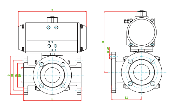
GB PN16 Main dimensions table (Unit: mm)
|
SIZE |
L |
L1 |
D2 |
D1 |
D |
N-ø d |
DA |
SR |
||
|
H |
Z |
H |
Z |
|||||||
|
DN15 |
150 |
75 |
46 |
65 |
95 |
4-ø 14 |
150 |
147 |
170 |
168 |
|
DN20 |
160 |
80 |
56 |
75 |
105 |
4-ø 14 |
170 |
168 |
190 |
204 |
|
DN25 |
180 |
90 |
65 |
85 |
115 |
4-ø 14 |
190 |
184 |
210 |
262 |
|
DN32 |
200 |
100 |
76 |
100 |
140 |
4-ø 18 |
210 |
204 |
235 |
268 |
|
DN40 |
220 |
110 |
84 |
110 |
150 |
4-ø 18 |
240 |
262 |
290 |
296 |
|
DN50 |
240 |
120 |
99 |
125 |
165 |
4-ø 18 |
270 |
268 |
315 |
390 |
|
DN65 |
260 |
130 |
118 |
145 |
185 |
8-ø 18 |
215 |
296 |
360 |
454 |
|
DN80 |
280 |
140 |
132 |
160 |
200 |
8-ø 18 |
390 |
454 |
420 |
525 |
|
DN100 |
320 |
160 |
156 |
180 |
220 |
8-ø 18 |
450 |
525 |
475 |
532 |
|
DN125 |
380 |
190 |
184 |
210 |
250 |
8-ø 18 |
500 |
532 |
530 |
610 |
|
DN150 |
440 |
220 |
211 |
240 |
285 |
8-ø 22 |
570 |
610 |
606 |
722 |
| DN200 | 550 | 275 | 266 | 295 | 340 | 12-ø 22 | 690 | 722 | 726 | 830 |
ELECTRIC THREE-WAY FLANGE BALL VALVE
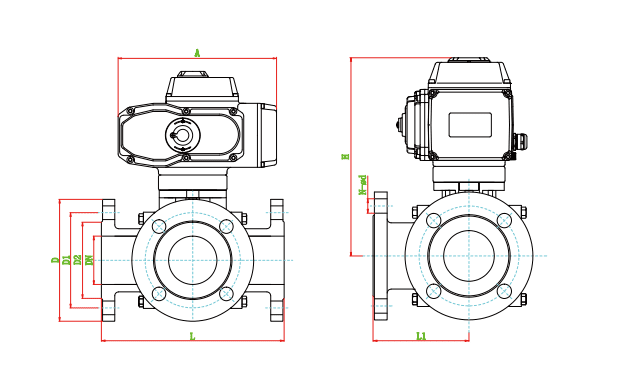
GB PN16 Main dimensions table (Unit: mm)
|
SIZE |
L |
L1 |
D2 |
D1 |
D |
N-ø d |
A |
H |
SIZE |
|
DN15 |
150 |
75 |
46 |
65 |
95 |
4-ø 14 |
165 |
200 |
SPD05 |
|
DN20 |
160 |
80 |
56 |
75 |
105 |
4-ø 14 |
165 |
210 |
SPD05 |
|
DN25 |
180 |
90 |
65 |
85 |
115 |
4-ø 14 |
212 |
240 |
SPD10 |
|
DN32 |
200 |
100 |
76 |
100 |
140 |
4-ø 18 |
212 |
250 |
SPD10 |
|
DN40 |
220 |
110 |
84 |
110 |
150 |
4-ø 18 |
259 |
310 |
SPD20 |
|
DN50 |
240 |
120 |
99 |
125 |
165 |
4-ø 18 |
259 |
320 |
SPD20 |
|
DN65 |
260 |
130 |
118 |
145 |
185 |
8-ø 18 |
259 |
335 |
SPD40 |
|
DN80 |
280 |
140 |
132 |
160 |
200 |
8-ø 18 |
259 |
365 |
SPD60 |
|
DN100 |
320 |
160 |
156 |
180 |
220 |
8-ø 18 |
284 |
420 |
SPD100 |
|
DN125 |
380 |
190 |
184 |
210 |
250 |
8-ø 18 |
284 |
440 |
SPD200 |
|
DN150 |
440 |
220 |
211 |
240 |
285 |
8-ø 22 |
284 |
470 |
SPD200 |
|
DN200 |
550 |
275 |
266 |
295 |
340 |
12-ø 22 |
500 |
700 |
SPD400 |
TEE THREAD BALL VALVE
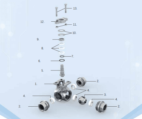
|
Serial number |
Part Name |
material |
|
1 |
Body |
CF8、CF8M、CF3M |
|
2 |
Bonnet |
CF8、CF8M、CF3M |
|
3 |
Ball body |
SS304、SS316、SS316L |
|
4 |
Seat |
PTFE 、PPL |
|
5 |
Stem |
SS304、SS316、SS316L |
|
6 |
Inverted seal |
PTFE、PPL |
|
7 |
O-ring |
VITON |
|
8 |
Filler |
PTFE、PPL |
|
9 |
Filling clamping ring |
SS304 |
|
10 |
Butterfly spring |
SS304 |
|
11 |
NUT |
SS304 |
|
12 |
Gland of valve |
CF8 |
|
13 |
Screw |
SS304 |
Product structure design feature
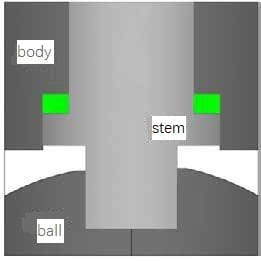
Valve stem anti-blowing structure design (see picture 1)
Valve stem anti-blowing structure design, the lower end is larger and the upper end is smaller Under the positioning of the upper-end cover and screws, even in the valve cavity is abnormal In this case, it can also ensures that the valve stem will not be blown out by the medium.
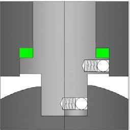
Anti-static design(See picture 2)
The fixed ball valve adopts an anti-static design to make the ball, stem and valve The body forms an electrostatic channel. So that the ball and the seat are switched During the process, static electricity generated by friction is led to the ground through the valve body, Preventing the risk of fire or explosion caused by static sparks.
KV rated
|
SIZE |
DN15 |
DN20 |
DN25 |
DN32 |
DN40 |
DN50 |
|
Kv |
13 |
21 |
38 |
72 |
112 |
170 |
Soft seal torque table (N.m)
|
SIZE |
DN15 |
DN20 |
DN25 |
DN32 |
DN40 |
DN50 |
|
PN16 |
4 |
6 |
10 |
20 |
26 |
32 |
|
PN25 |
7 |
10 |
14 |
22 |
30 |
36 |
|
PN40 |
11 |
14 |
20 |
48 |
60 |
70 |
|
PN63 |
16 |
30 |
60 |
100 |
130 |
160 |
|
SIZE |
D | |